

Question: Please use matlab and follow the flowchart Problem Cylindrical steel tanks have many outdoor uses. They are used in oil and gas refining, food production,
Please use matlab and follow the flowchart
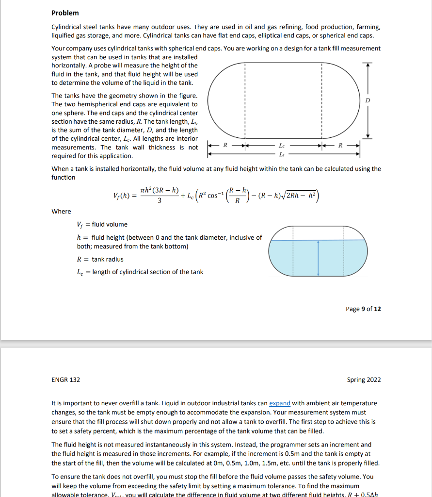
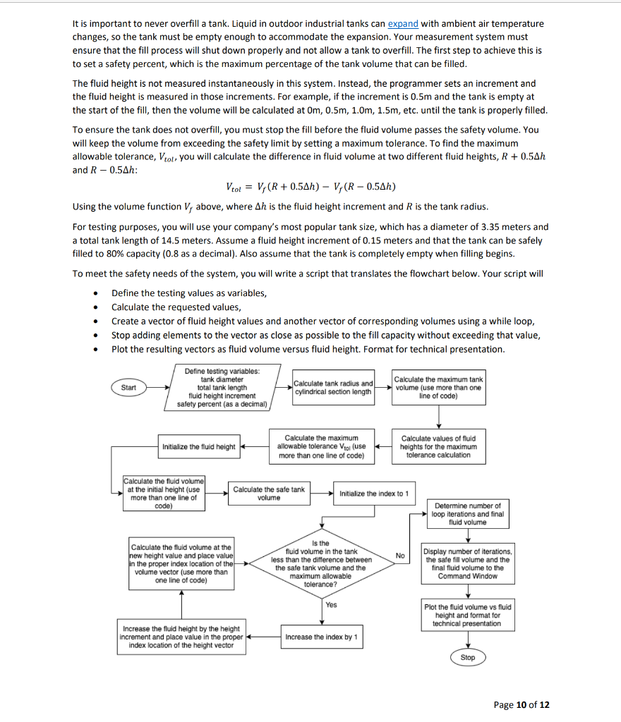
Problem Cylindrical steel tanks have many outdoor uses. They are used in oil and gas refining, food production, farming, liquified gas storage, and more. Cylindrical tanks can have flat end caps, elliptical end caps, or spherical end caps. Your company uses cylindrical tanks with spherical end caps. You are working on a design for a tank fill measurement system that can be used in tanks that are installed horizontally. A probe will measure the height of the fluid in the tank, and that fluid height will be used to determine the volume of the liquid in the tank. The tanks have the geometry shown in the figure. The two hemispherical end caps are equivalent to one sphere. The end caps and the cylindrical center section have the same radius, R. The tank length, L, is the sum of the tank diameter, D, and the length of the cylindrical center, Lc. All lengths are interior measurements. The tank wall thickness is not R- Lc R required for this application. LO When a tank is installed horizontally, the fluid volume at any fluid height within the tank can be calculated using the function Tth (3R - h) R-h V; (h) = + LcR2 cos -1 (R2 - (R-h) 2Rh-h2 3 Where ) Vi = fluid volume h = fluid height (between 0 and the tank diameter, inclusive of both; measured from the tank bottom) R = tank radius Le = length of cylindrical section of the tank Page 9 of 12 ENGR 132 Spring 2022 It is important to never overfill a tank. Liquid in outdoor industrial tanks can expand with ambient air temperature changes, so the tank must be empty enough to accommodate the expansion. Your measurement system must ensure that the fill process will shut down properly and not allow a tank to overfill. The first step to achieve this is to set a safety percent, which is the maximum percentage of the tank volume that can be filled. The fluid height is not measured instantaneously in this system. Instead, the programmer sets an increment and the fluid height is measured in those increments. For example, if the increment is 0.5m and the tank is empty at the start of the fill, then the volume will be calculated at Om, 0.5m, 1.0m, 1.5m, etc. until the tank is properly filled. To ensure the tank does not overfill, you must stop the fill before the fluid volume passes the safety volume. You will keep the volume from exceeding the safety limit by setting a maximum tolerance. To find the maximum allowable tolerance. V... You will calculate the difference in fluid volume at two different fluid heights. R +0.5Ah It is important to never overfill a tank. Liquid in outdoor industrial tanks can expand with ambient air temperature changes, so the tank must be empty enough to accommodate the expansion. Your measurement system must ensure that the fill process will shut down properly and not allow a tank to overfill. The first step to achieve this is to set a safety percent, which is the maximum percentage of the tank volume that can be filled. The fluid height is not measured instantaneously in this system. Instead, the programmer sets an increment and the fluid height is measured in those increments. For example, if the increment is 0.5m and the tank is empty at the start of the fill, then the volume will be calculated at Om, 0.5m, 1.0m, 1.5m, etc. until the tank is properly filled. To ensure the tank does not overfill, you must stop the fill before the fluid volume passes the safety volume. You will keep the volume from exceeding the safety limit by setting a maximum tolerance. To find the maximum allowable tolerance, Vtot, you will calculate the difference in fluid volume at two different fluid heights, R + 0.5Ah and R -0.54h: Vtol = V (R+ 0.5Ah) - V;(R - 0.5Ah) Using the volume function V, above, where Ah is the fluid height increment and R is the tank radius. For testing purposes, you will use your company's most popular tank size, which has a diameter of 3.35 meters and a total tank length of 14.5 meters. Assume a fluid height increment of 0.15 meters and that the tank can be safely filled to 80% capacity (0.8 as a decimal). Also assume that the tank is completely empty when filling begins. To meet the safety needs of the system, you will write a script that translates the flowchart below. Your script will Define the testing values as variables, Calculate the requested values, Create a vector of fluid height values and another vector of corresponding volumes using a while loop, Stop adding elements to the vector as close as possible to the fill capacity without exceeding that value, Plot the resulting vectors as fluid volume versus fluid height. Format for technical presentation. Start Define testing variables: tank diameter total tank length fluid height increment safety percent (as a decimal) Calculate tank radius and volume (use more than one Calculate the maximum tank cylindrical section length line of code) Initialize the fluid height Calculate the maximum allowable tolerance to use more than one line of code) Calculate values of fluid heights for the maximum tolerance calculation Calculate the fluid volume at the initial height (use more than one line of code) Calculate the safe tank volume Initialize the index to 1 Determine number of loop iterations and final fluid volume No Calculate the fluid volume at the new height value and place value in the proper index location of the volume vector (use more than one line of code) Is the fluid volume in the tank less than the difference between the safe tank volume and the maximum allowable tolerance? Display number of iterations, the safe fill volume and the final fluid volume to the Command Window Yes Plot the fluid volume vs fluid height and format for technical presentation Increase the fluid height by the height increment and place value in the proper index location of the height vector Increase the index by 1 Stop Page 10 of 12 Problem Cylindrical steel tanks have many outdoor uses. They are used in oil and gas refining, food production, farming, liquified gas storage, and more. Cylindrical tanks can have flat end caps, elliptical end caps, or spherical end caps. Your company uses cylindrical tanks with spherical end caps. You are working on a design for a tank fill measurement system that can be used in tanks that are installed horizontally. A probe will measure the height of the fluid in the tank, and that fluid height will be used to determine the volume of the liquid in the tank. The tanks have the geometry shown in the figure. The two hemispherical end caps are equivalent to one sphere. The end caps and the cylindrical center section have the same radius, R. The tank length, L, is the sum of the tank diameter, D, and the length of the cylindrical center, Lc. All lengths are interior measurements. The tank wall thickness is not R- Lc R required for this application. LO When a tank is installed horizontally, the fluid volume at any fluid height within the tank can be calculated using the function Tth (3R - h) R-h V; (h) = + LcR2 cos -1 (R2 - (R-h) 2Rh-h2 3 Where ) Vi = fluid volume h = fluid height (between 0 and the tank diameter, inclusive of both; measured from the tank bottom) R = tank radius Le = length of cylindrical section of the tank Page 9 of 12 ENGR 132 Spring 2022 It is important to never overfill a tank. Liquid in outdoor industrial tanks can expand with ambient air temperature changes, so the tank must be empty enough to accommodate the expansion. Your measurement system must ensure that the fill process will shut down properly and not allow a tank to overfill. The first step to achieve this is to set a safety percent, which is the maximum percentage of the tank volume that can be filled. The fluid height is not measured instantaneously in this system. Instead, the programmer sets an increment and the fluid height is measured in those increments. For example, if the increment is 0.5m and the tank is empty at the start of the fill, then the volume will be calculated at Om, 0.5m, 1.0m, 1.5m, etc. until the tank is properly filled. To ensure the tank does not overfill, you must stop the fill before the fluid volume passes the safety volume. You will keep the volume from exceeding the safety limit by setting a maximum tolerance. To find the maximum allowable tolerance. V... You will calculate the difference in fluid volume at two different fluid heights. R +0.5Ah It is important to never overfill a tank. Liquid in outdoor industrial tanks can expand with ambient air temperature changes, so the tank must be empty enough to accommodate the expansion. Your measurement system must ensure that the fill process will shut down properly and not allow a tank to overfill. The first step to achieve this is to set a safety percent, which is the maximum percentage of the tank volume that can be filled. The fluid height is not measured instantaneously in this system. Instead, the programmer sets an increment and the fluid height is measured in those increments. For example, if the increment is 0.5m and the tank is empty at the start of the fill, then the volume will be calculated at Om, 0.5m, 1.0m, 1.5m, etc. until the tank is properly filled. To ensure the tank does not overfill, you must stop the fill before the fluid volume passes the safety volume. You will keep the volume from exceeding the safety limit by setting a maximum tolerance. To find the maximum allowable tolerance, Vtot, you will calculate the difference in fluid volume at two different fluid heights, R + 0.5Ah and R -0.54h: Vtol = V (R+ 0.5Ah) - V;(R - 0.5Ah) Using the volume function V, above, where Ah is the fluid height increment and R is the tank radius. For testing purposes, you will use your company's most popular tank size, which has a diameter of 3.35 meters and a total tank length of 14.5 meters. Assume a fluid height increment of 0.15 meters and that the tank can be safely filled to 80% capacity (0.8 as a decimal). Also assume that the tank is completely empty when filling begins. To meet the safety needs of the system, you will write a script that translates the flowchart below. Your script will Define the testing values as variables, Calculate the requested values, Create a vector of fluid height values and another vector of corresponding volumes using a while loop, Stop adding elements to the vector as close as possible to the fill capacity without exceeding that value, Plot the resulting vectors as fluid volume versus fluid height. Format for technical presentation. Start Define testing variables: tank diameter total tank length fluid height increment safety percent (as a decimal) Calculate tank radius and volume (use more than one Calculate the maximum tank cylindrical section length line of code) Initialize the fluid height Calculate the maximum allowable tolerance to use more than one line of code) Calculate values of fluid heights for the maximum tolerance calculation Calculate the fluid volume at the initial height (use more than one line of code) Calculate the safe tank volume Initialize the index to 1 Determine number of loop iterations and final fluid volume No Calculate the fluid volume at the new height value and place value in the proper index location of the volume vector (use more than one line of code) Is the fluid volume in the tank less than the difference between the safe tank volume and the maximum allowable tolerance? Display number of iterations, the safe fill volume and the final fluid volume to the Command Window Yes Plot the fluid volume vs fluid height and format for technical presentation Increase the fluid height by the height increment and place value in the proper index location of the height vector Increase the index by 1 Stop Page 10 of 12
Step by Step Solution
There are 3 Steps involved in it

Get step-by-step solutions from verified subject matter experts