

Question: Plz need help using Quartus program In this lab, you are going design an add/subtract accumulator. Accumulators are very commonly used state machines in all
Plz need help using Quartus program
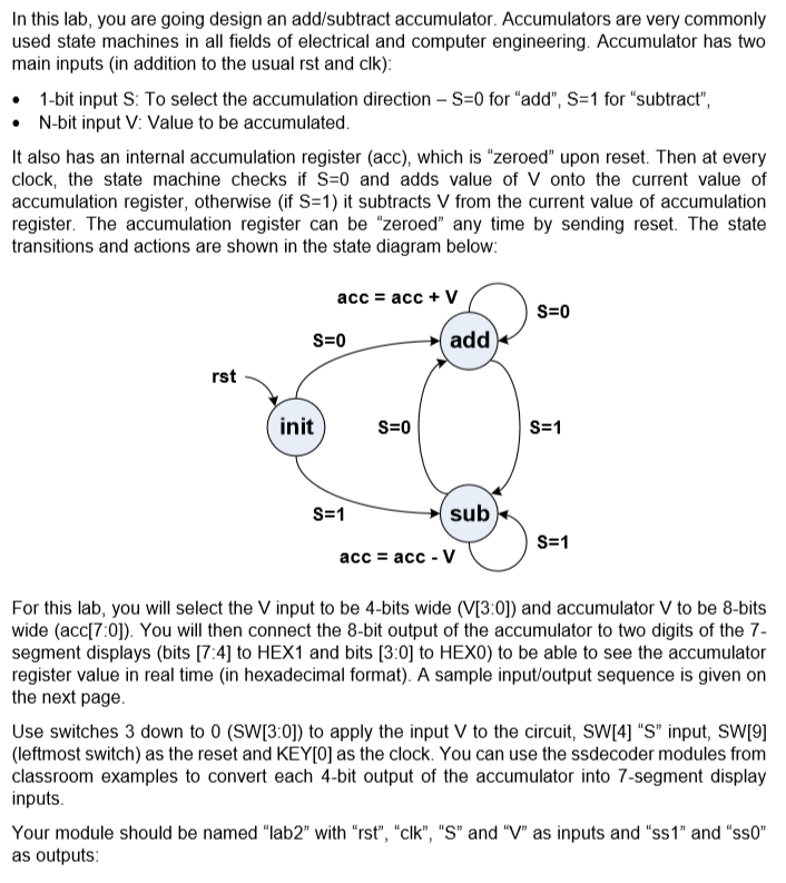
In this lab, you are going design an add/subtract accumulator. Accumulators are very commonly used state machines in all fields of electrical and computer engineering. Accumulator has two main inputs (in addition to the usual rst and clk): 1-bit input S: To select the accumulation direction - S=0 for "add", S=1 for "subtract", N-bit input V: Value to be accumulated It also has an internal accumulation register (acc), which is "zeroed upon reset. Then at every clock, the state machine checks if S=0 and adds value of V onto the current value of accumulation register, otherwise (if S=1) it subtracts V from the current value of accumulation register. The accumulation register can be "zeroed" any time by sending reset. The state transitions and actions are shown in the state diagram below: acc = acc + V S=0 S=0 add init S=0 S=1 S=1 sub S=1 acc = acc - V For this lab, you will select the V input to be 4-bits wide (V[3:0]) and accumulator V to be 8-bits wide (acc[70]). You will then connect the 8-bit output of the accumulator to two digits of the 7- segment displays (bits [7:4] to HEX1 and bits [3:0] to HEXO) to be able to see the accumulator register value in real time (in hexadecimal format). A sample input/output sequence is given on the next page Use switches 3 down to O (SW[3:0]) to apply the input V to the circuit, SW[4] "S" input, SW[9] (leftmost switch) as the reset and KEY[O] as the clock. You can use the ssdecoder modules from classroom examples to convert each 4-bit output of the accumulator into 7-segment display inputs Your module should be named "lab2" with "rst", "clk", "S" and "V" as inputs and "ss 1" and "sso" as outputs: In this lab, you are going design an add/subtract accumulator. Accumulators are very commonly used state machines in all fields of electrical and computer engineering. Accumulator has two main inputs (in addition to the usual rst and clk): 1-bit input S: To select the accumulation direction - S=0 for "add", S=1 for "subtract", N-bit input V: Value to be accumulated It also has an internal accumulation register (acc), which is "zeroed upon reset. Then at every clock, the state machine checks if S=0 and adds value of V onto the current value of accumulation register, otherwise (if S=1) it subtracts V from the current value of accumulation register. The accumulation register can be "zeroed" any time by sending reset. The state transitions and actions are shown in the state diagram below: acc = acc + V S=0 S=0 add init S=0 S=1 S=1 sub S=1 acc = acc - V For this lab, you will select the V input to be 4-bits wide (V[3:0]) and accumulator V to be 8-bits wide (acc[70]). You will then connect the 8-bit output of the accumulator to two digits of the 7- segment displays (bits [7:4] to HEX1 and bits [3:0] to HEXO) to be able to see the accumulator register value in real time (in hexadecimal format). A sample input/output sequence is given on the next page Use switches 3 down to O (SW[3:0]) to apply the input V to the circuit, SW[4] "S" input, SW[9] (leftmost switch) as the reset and KEY[O] as the clock. You can use the ssdecoder modules from classroom examples to convert each 4-bit output of the accumulator into 7-segment display inputs Your module should be named "lab2" with "rst", "clk", "S" and "V" as inputs and "ss 1" and "sso" as outputs
Step by Step Solution
There are 3 Steps involved in it

Get step-by-step solutions from verified subject matter experts