

Question: Power ON. Set the data select switches (D, C, B, and A) as shown in the truth table in Table 4-4. Apply a logical 1
Power ON. Set the data select switches (D, C, B, and A) as shown in the truth table in Table 4-4. Apply a logical 1 to the correct data input using an input switch. Observe the outputs W and Y. Record the 32 outputs in columns W and Y, Table 4-4.
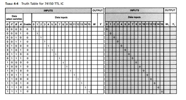
TABLE 4-4 Truth Table for 74150 TTL IC Data select switches DCBA Enable 0121 000001 0001 0010 0 0 1 0011 0 0100 0 0101 0 01 10 0 0111 0 1000 1001 0 1010 0 10 11 1100 0 11010 1110 0 1111 INPUTS OUTPUT Data inputs 456789 10 11 12 13 14 15 W, Y, INPUTS OUTPUT Data inputs 6 7 8 9 10 11 12 13 14 15 W Y 01 0 0 O O 0 0 O 0 0
Step by Step Solution
There are 3 Steps involved in it
1 Expert Approved Answer
Step: 1 Unlock

Question Has Been Solved by an Expert!
Get step-by-step solutions from verified subject matter experts
Step: 2 Unlock
Step: 3 Unlock