

Question: PRE - CALCULATIONS PART 1 . Emitter - Bias Configuration: Determining Choose from the given datasheet on the first page. = 2 0 0 Depend
PRECALCULATIONS
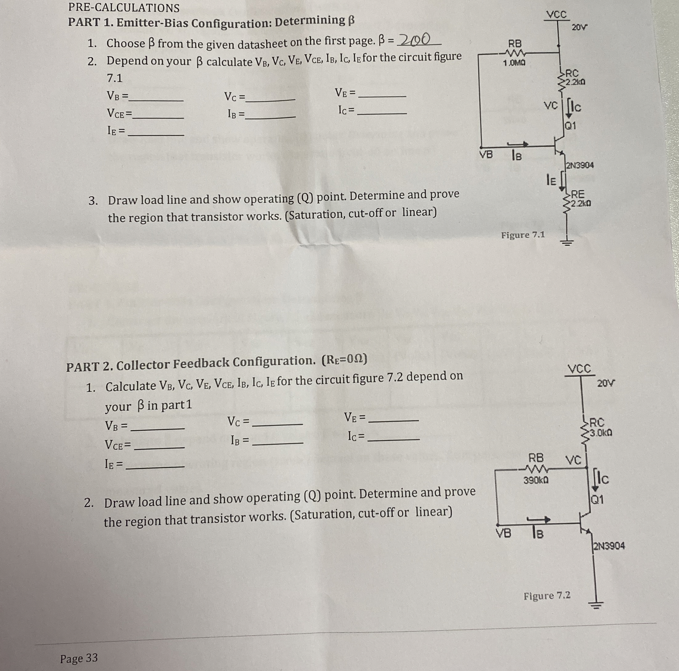
PART EmitterBias Configuration: Determining
Choose from the given datasheet on the first page.
Depend on your calculate for the circuit figure
Draw load line and show operating Q point. Determine and prove the region that transistor works. Saturation cutoff or linear
PART Collector Feedback Configuration.
Calculate for the circuit figure depend on your in part
Draw load line and show operating point. Determine and prove the region that transistor works. Saturation cutoff or linear
Page
Step by Step Solution
There are 3 Steps involved in it
1 Expert Approved Answer
Step: 1 Unlock

Question Has Been Solved by an Expert!
Get step-by-step solutions from verified subject matter experts
Step: 2 Unlock
Step: 3 Unlock