

Question: Prob. 3.7-3. A pipe-rod system with flanges at ends A and C was supposed to fit exactly between two rigid walls, as shown in
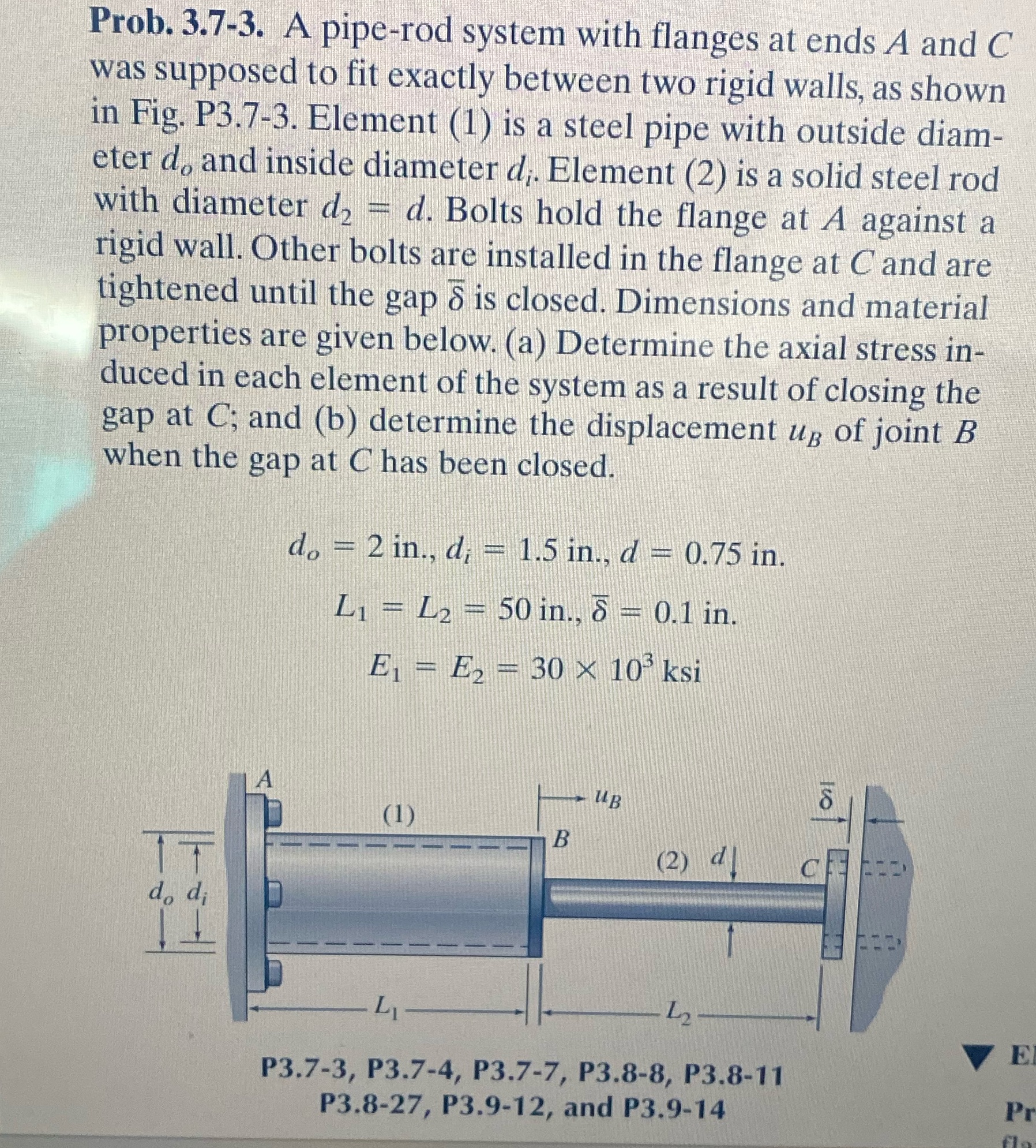
Prob. 3.7-3. A pipe-rod system with flanges at ends A and C was supposed to fit exactly between two rigid walls, as shown in Fig. P3.7-3. Element (1) is a steel pipe with outside diam- eter d, and inside diameter d;. Element (2) is a solid steel rod with diameter d = d. Bolts hold the flange at A against a rigid wall. Other bolts are installed in the flange at C and are tightened until the gap 5 is closed. Dimensions and material properties are given below. (a) Determine the axial stress in- duced in each element of the system as a result of closing the gap at C; and (b) determine the displacement up of joint B when the gap at C has been closed. do = 2 in., d; = 1.5 in., d = 0.75 in. 8 L = L = 50 in., = 0.1 in. E = E = 30 10 ksi www E2 IT A do di L UB (1) B (2) 12 P3.7-3, P3.7-4, P3.7-7, P3.8-8, P3.8-11 P3.8-27, P3.9-12, and P3.9-14 81 E Pr
Step by Step Solution
There are 3 Steps involved in it

Get step-by-step solutions from verified subject matter experts