

Question: Problem 1 ( 2 0 points ) Consider the following longitudinal model of a viaduct represented in Figure 1 . ( a ) Consider that
Problem points
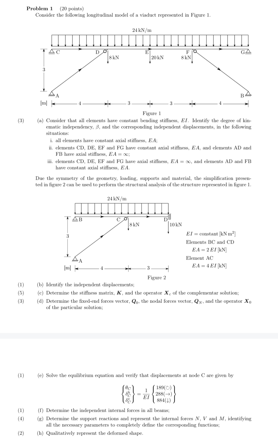
Consider the following longitudinal model of a viaduct represented in Figure
a Consider that all elements have constant bending stiffness, EI Identify the degree of kinematic independency, and the corresponding independent displacements, in the following situations:
i all elements have constant axial stiffness, ;
ii elements CD DE EF and FG have constant axial stiffness, and elements AD and FB have axial stiffness, ;
iii. elements CD DE EF and FG have axial stiffness, and elements AD and FB have constant axial stiffness,
Due the symmetry of the geometry, loading, supports and material, the simplification presented in figure can be used to perform the structural analysis of the structure represented in figure
b Identify the independent displacements;
c Determine the stiffness matrix, and the operator of the complementar solution;
d Determine the fixedend forces vector, the nodal forces vector, and the operator of the particular solution;
constant
Elements BC and CD
Element AC
Structural Mechanics
Continous assessment: Displacement method II
st October
e Solve the equilibrium equation and verify that displacements at node C are given by
f Determine the independent internal forces in all beams;
g Determine the support reactions and represent the internal forces and identifying all the necessary parameters to completely define the corresponding functions;
h Qualitatively represent the deformed shape.
Problem points
Consider the following longitudinal model of a viaduct represented in Figure
a Consider that all elements have constant bending stiffness, EI Identify the degree of kinematic independency, and the corresponding independent displacements, in the following situations:
i all elements have constant axial stiffness, ;
ii elements CD DE EF and FG have constant axial stiffness, and elements AD and FB have axial stiffness, ;
iii. elements CD DE EF and FG have axial stiffness, and elements AD and FB have constant axial stiffness,
Due the symmetry of the geometry, loading, supports and material, the simplification presented in figure can be used to perform the structural analysis of the structure represented in figure
b Identify the independent displacements;
c Determine the stiffness matrix, and the operator of the complementar solution;
d Determine the fixedend forces vector, the nodal forces vector, and the operator of the particular solution;
constant
Elements and
Element
e Solve the equilibrium equation and verify that displacements at node C are given by
f Determine the independent internal forces in all beams;
g Determine the support reactions and represent the internal forces and identifying all the necessary parameters to completely define the corresponding functions;
h Qualitatively represent the deformed shape.
Step by Step Solution
There are 3 Steps involved in it
1 Expert Approved Answer
Step: 1 Unlock

Question Has Been Solved by an Expert!
Get step-by-step solutions from verified subject matter experts
Step: 2 Unlock
Step: 3 Unlock