

Question: Problem 1 ( 3 0 points ) You are designing a water storage system for the town of Tolmin, Slovenla that comprises three reservoirs as
Problem points
You are designing a water storage system for the town of Tolmin, Slovenla that comprises three reservoirs as shown in schematic bird's eve vew below. The water elevations of the three reservoirs are as follows: and elerations The elevation of node where the pipes converge is
Node is supposed to storepass enough water to provide for the water demands of the town network; this network will be analyzed in Problem The flowrate that needs to be available at node is This means that at
Ignore minor losses and do not update friction factors after each iteration.
The characteristics of the three plpes are in the table below:
tableThe characteristics of the three ploses.are,RJRRDiameter Length Rouphess
a Perform a maximum of iterations and calculate the flowrates going through this system and the head at node You will need this head for Problem
b Perform all appropriate calculat
Problem points
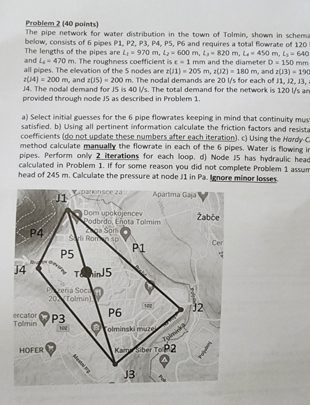
The pipe network for water distribution in the town of Tolmin, shown in schema below, consists of pipes P P P P P P and requires a total flowrate of The lengths of the pipes are and The roughness coefficient is and the diameter all pipes. The elevation of the nodes are and and The nodal demands are for each of J The nodal demand for is The total demand for the network is an provided through node as described in Problem
a Select initial guesses for the pipe flowrates keeping in mind that continuity mus satisfied. b Using all pertinent information calculate the friction factors and resistance coefficients do not update these numbers after each iteration c Using the HardyCross method calculate manually the flowrate in each of the pipes. Water is flowing ir pipes. Perform only iterations for each loop. d Node has hydraulic head calculated in Problem If for some reason you did not complete Problem assum head of m Calculate the pressure at node J in Pa Ignore minor losses.ions manually and draw the HGL and EGL curves for pipe RI
show all steps and use DarcyW equation
Step by Step Solution
There are 3 Steps involved in it
1 Expert Approved Answer
Step: 1 Unlock

Question Has Been Solved by an Expert!
Get step-by-step solutions from verified subject matter experts
Step: 2 Unlock
Step: 3 Unlock