

Question: Problem 1 ( 3 5 points ) The frame shown in Figure 1 has a pin support at ( A ) , a
Problem points
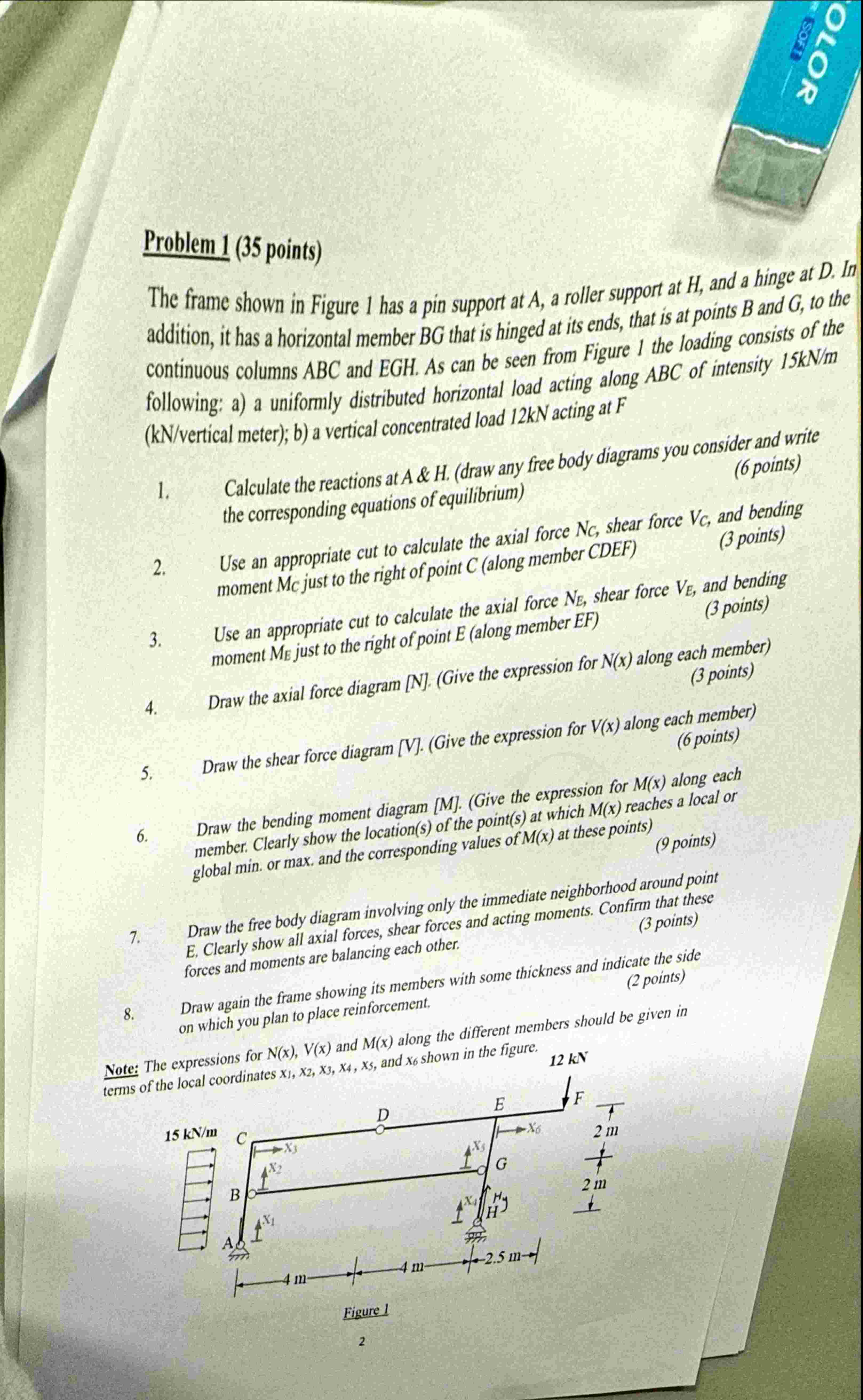
The frame shown in Figure has a pin support at A a roller support at H and a hinge at D In addition, it has a horizontal member B G that is hinged at its ends, that is at points B and G to the continuous columns A B C and E G H As can be seen from Figure the loading consists of the following: a a uniformly distributed horizontal load acting along A B C of intensity mathrmkNmathrmmmathrmKN vertical meter; b a vertical concentrated load kN acting at F
Calculate the reactions at A & H draw any free body diagrams you consider and write the corresponding equations of equilibrium
Use an appropriate cut to calculate the axial force NC shear force VC and bending moment M c just to the right of point C along member CDEF
Use an appropriate cut to calculate the axial force NE shear force VE and bending moment ME just to the right of point E along member E F
Draw the axial force diagram NGive the expression for Nx along each member
Draw the shear force diagram VGive the expression for Vx along each member
points
Draw the bending moment diagram MGive the expression for Mx along each member. Clearly show the locations of the points at which Mx reaches a local or global min. or max. and the corresponding values of Mx at these points
points
Draw the free body diagram involving only the immediate neighborhood around point E Clearly show all axial forces, shear forces and acting moments. Confirm that these forces and moments are balancing each other.
Draw again the frame showing its members with some thickness and indicate the side points on which you plan to place reinforcement.
Note: The expressions for Nx Vx and Mx along the different members should be given in terms
Step by Step Solution
There are 3 Steps involved in it
1 Expert Approved Answer
Step: 1 Unlock

Question Has Been Solved by an Expert!
Get step-by-step solutions from verified subject matter experts
Step: 2 Unlock
Step: 3 Unlock