

Question: Problem 1: (30 points): The figure below shows a unipolar PWM converter with a switching frequency of 50 kHz. Consider the following two cases:
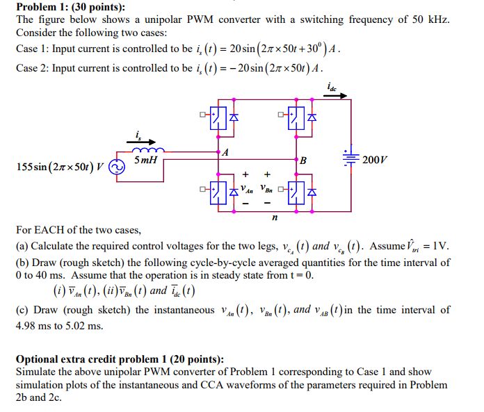
Problem 1: (30 points): The figure below shows a unipolar PWM converter with a switching frequency of 50 kHz. Consider the following two cases: Case 1: Input current is controlled to be i, (t) = 20 sin (2750t+30) 4. Case 2: Input current is controlled to be i, (t) = -20 sin (2750t) A. 155 sin (27 50t) V 5mH CH (i) VAR (t), (ii) VBM (t) and ide (t) An CH A + + An CH B CH n 200V For EACH of the two cases, (a) Calculate the required control voltages for the two legs, v. (t) and vc (t). Assume = 1V. (b) Draw (rough sketch) the following cycle-by-cycle averaged quantities for the time interval of 0 to 40 ms. Assume that the operation is in steady state from t = 0. An AB (c) Draw (rough sketch) the instantaneous VAN (1), VBR (1), and VB (t) in the time interval of 4.98 ms to 5.02 ms. Optional extra credit problem 1 (20 points): Simulate the above unipolar PWM converter of Problem 1 corresponding to Case 1 and show simulation plots of the instantaneous and CCA waveforms of the parameters required in Problem 2b and 2c.
Step by Step Solution
3.36 Rating (162 Votes )
There are 3 Steps involved in it
To solve the problem we need to analyze the given PWM converter for each case Lets break it down ste... View full answer

Get step-by-step solutions from verified subject matter experts