

Question: Problem 1 (7 points) For parts a, b, and c, draw the circuit as described in the corresponding Verilog snippet. You can do it using
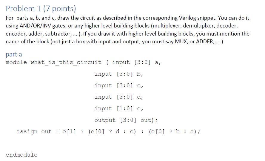
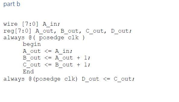
Problem 1 (7 points) For parts a, b, and c, draw the circuit as described in the corresponding Verilog snippet. You can do it using AND/OR/INV gates, or any higher level building blocks (multiplexer, demultiplxer, decoder, encoder, adder, subtractor, ... ). If you draw it with higher level building blocks, you must mention the name of the block (not just a box with input and output, you must say MUX, or ADDER, ....) part a module what_is_this_circuit ( input [3:0] a, input [3:0] b, input [3:0] c, input [3:0] d, input (1:0) e, output (3:0) out); assign out = e [1] ? (e[0] ? d : c): (e[0] ? b: a); endmodule part b wire [7:0] A_in; reg[7:0] A_out, B_out, C_out, D_out; always @ ( posedge clk ) begin A_out
Step by Step Solution
There are 3 Steps involved in it

Get step-by-step solutions from verified subject matter experts