

Question: Problem # 1 : Build the circuit like in the figure below. The input signal V 5 = 2 0 V p p f =
Problem #:
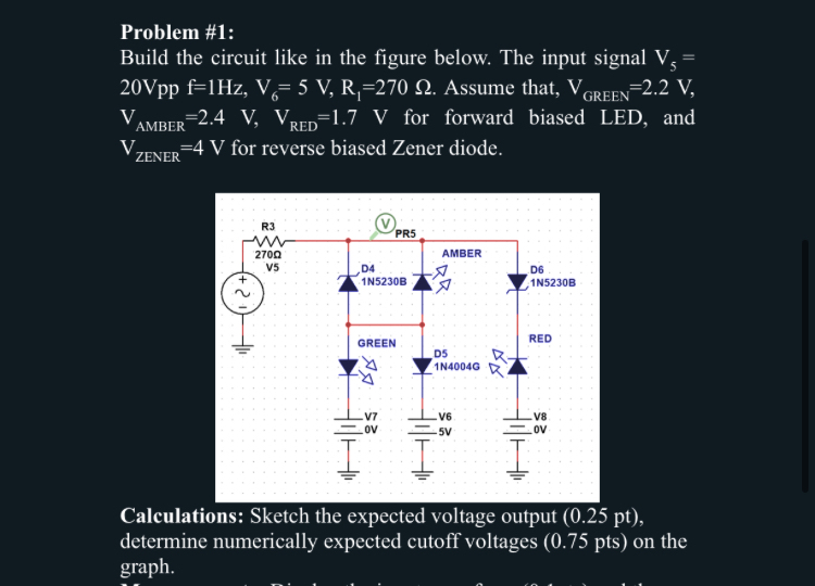
Build the circuit like in the figure below. The input signal Assume that, for forward biased LED, and for reverse biased Zener diode.
Calculations: Sketch the expected voltage output pt determine numerically expected cutoff voltages pts on the graph.
Step by Step Solution
There are 3 Steps involved in it
1 Expert Approved Answer
Step: 1 Unlock

Question Has Been Solved by an Expert!
Get step-by-step solutions from verified subject matter experts
Step: 2 Unlock
Step: 3 Unlock