

Question: Problem 1 : Cable Bridge Structure 1 . A wire rope bridge is being designed to span 1 1 0 across a small 3 0
Problem : Cable Bridge Structure
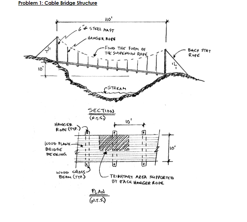
A wire rope bridge is being designed to span across a small deep ravine and
stream. Using graphic statics as in Chapter of Form and Forces, find the form of a
suspended rope for the bridge. Design for the following criteria:
Shape the suspended cable wire rope for a maximum force of pounds on the
main span
Two tall diameter steel masts support the suspended rope at each end
One side of the ravine is higher than the other
Hanger ropes support a wide bridge deck. The deck is made of heavy timber
planking spanning to cross members that are in turn supported by the hanger ropes.
The total dead and live load of the bridge is pounds per square foot.
Use a graphic scale of for the form diagram and lbs for the force
polygon
Using a scale of lbs find the force in the supporting backstay ropes after finding
the forces in the suspended cable, backstay and mast.
Given an allowable stress on the wire rope of psi, how large of a diameter is required?
Round your answer up to the nearest
Derive two more forms for the suspended wire rope cable using the same closing string as
in part but locate the pole an arbitrary distance to the left and to the right of the first pole.
Draw these diagrams on the same load line as the first diagram, but use a different color for
each. Transfer those to the form diagram in the same color as used on the force polygon.
Answer the following questions:
What conclusion can you arrive at regarding the forces in each suspended rope design?
Which is design will have the lowest cable forces?
What is the height above the deck at the lowest point of the cable sag for each design
case?
What are the required sizes of the wire ropes for these forms, using the same allowable
stress values as the first design?
Which design is most visually pleasing?
Sketch a suggested detail for supporting the cables at the top of the mast, including labels
for materials and sizes of the primary components. Refer to details in Chapter of Form and
Forces for inspiration.
Step by Step Solution
There are 3 Steps involved in it
1 Expert Approved Answer
Step: 1 Unlock

Question Has Been Solved by an Expert!
Get step-by-step solutions from verified subject matter experts
Step: 2 Unlock
Step: 3 Unlock