

Question: Problem 1 : Design a fourbar linkage using Solidworks that is capable of positioning the 7 0 mm - long coupler at the three positions
Problem :
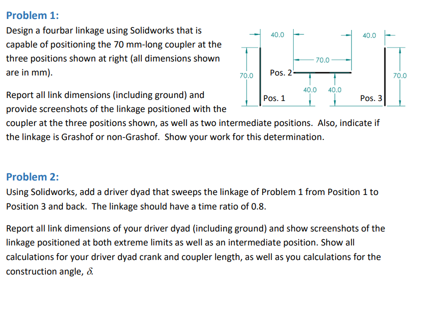
Design a fourbar linkage using Solidworks that is
capable of positioning the mm long coupler at the
three positions shown at right all dimensions shown
are in mm
Report all link dimensions including ground and
provide screenshots of the linkage positioned with the
coupler at the three positions shown, as well as two intermediate positions. Also, indicate if
the linkage is Grashof or nonGrashof. Show your work for this determination.
Problem :
Using Solidworks, add a driver dyad that sweeps the linkage of Problem from Position to
Position and back. The linkage should have a time ratio of
Report all link dimensions of your driver dyad including ground and show screenshots of the
linkage positioned at both extreme limits as well as an intermediate position. Show all
calculations for your driver dyad crank and coupler length, as well as you calculations for the
construction angle,
Step by Step Solution
There are 3 Steps involved in it
1 Expert Approved Answer
Step: 1 Unlock

Question Has Been Solved by an Expert!
Get step-by-step solutions from verified subject matter experts
Step: 2 Unlock
Step: 3 Unlock