

Question: Problem 1 . Ethernet Frame ( 10 pt.) Describe the Ethernet standard frame structure and explain the role of each field defined in the structure.
Problem 1. Ethernet Frame (10 pt.)
Describe the Ethernet standard frame structure and explain the role of each field defined in the structure.
Problem 2. 2D Parity (10 pt.)
Suppose the information portion of a packet contains 10 bytes as follows:
D: 01001100 01101001 01101110 01101011 00100000
01001100 01100001 01111001 01100101 01110010
Suppose an odd parity scheme is being used. What would be the value of the field containing the parity bits be for the case of a two-dimensional parity scheme? Assume the bits in D are divided into 10 rows and 8 columns (i.e., each byte is a row).
Problem 3. CRC (10 pt.)
Assume that the message M: 1101011011 (10 bits) has to be transmitted and the generator function G: 10011 (5 bits) is used for error detection in the CRC scheme. Calculate the redundancy code. What will be the bit sequence that actually gets transmitted? Show your work.
Problem 4. LAN Addressing (20 pt.)
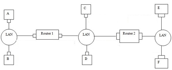
Consider the following three LANs interconnected by 2 routers. The table shows assigned IP addresses for hosts and routers in the network.
| Interface | IP address | MAC address |
| A | 129.128.0.100 | AA-12-34-56-78-90 |
| B | 129.128.0.101 | BB-12-34-56-78-90 |
| C | 129.128.1.100 | CC-12-34-56-78-90 |
| D | 129.128.1.101 | DD-12-34-56-78-90 |
| E | 129.128.2.100 | EE-12-34-56-78-90 |
| F | 129.128.2.101 | FF-12-34-56-78-90 |
| Router 1 left | 129.128.0.1 | 11-00-00-00-00-01 |
| Router 1 right | 129.128.1.1 | 11-00-00-00-00-02 |
| Router 2 left | 129.128.1.2 | 12-00-00-00-00-01 |
| Router 2 right | 129.128.2.1 | 12-00-00-00-00-02 |
Suppose Host A sends a datagram to Host E.
a. Give the source and destination MAC addresses in the frame encapsulating this IP datagram as the frame is transmitted from A to the left router. Also give the source and destination IP addresses in the IP datagram encapsulated within the frame.
b. Now give the source and destination MAC addresses in the frame encapsulating this IP datagram as the frame is transmitted from the left router to the right router. Also give the source and destination IP addresses in the IP datagram encapsulated within the frame.
c. Repeat the same thing as above a and b for the frame from the right router to E.
d. Now suppose that the two routers in the figure are replaced by switches. What are the source and the destination MAC addresses and the source and destination IP addresses in the packet transmitted from A (to E)?
Problem 5. Link State Routing (30 pt.)
Consider the following network.
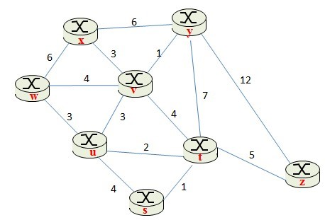
a. (16 pt.) With the indicated link costs, use Dijkstras shortest-path algorithm to compute the shortest path from w to all network nodes. Show how the algorithm works by computing the table below. Note: If there exists any tie in each step, choose the left-most column first.
| Step | N | D(s), p(s) | D(t), p(t) | D(u), p(u) | D(v), p(v) | D(x), p(x) | D(y), p(y) | D(z), p(z) |
| 0 | ||||||||
| 1 | ||||||||
| 2 | ||||||||
| 3 | ||||||||
| 4 | ||||||||
| 5 | ||||||||
| 6 | ||||||||
| 7 |
b. (7 pt.) Construct the shortest path tree from the above routing table
c. (7 pt.) Construct a forwarding table from the above routing table
| Destination | Link |
LAN Router 1 LAN Router 2 LAN
Step by Step Solution
There are 3 Steps involved in it

Get step-by-step solutions from verified subject matter experts