

Question: Problem 2 (25 pt.): Base on the following VHDL code library ieee use ieee.atd logic 1164.all entity full adder is end full adder architecture rtl
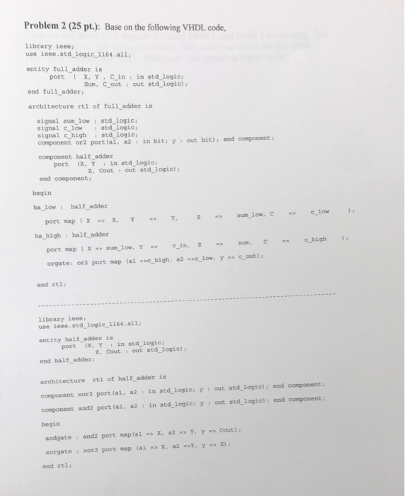
Problem 2 (25 pt.): Base on the following VHDL code library ieee use ieee.atd logic 1164.all entity full adder is end full adder architecture rtl of full_adder is port x.Y.C inin atd logie Sum, Cout : out std logic) signal aum low: atd logic signal c low atd logic signal c high atd logic component or2 port (ai, a2 in bitiy out bit) i end component: component half adder port (x, Y in std logic 2, Cout s out atd_logic)a end component: begin ha low i half adder ha high s half_adder orgate: or2 port map (al chigh, a2 low, ycout) end rtl library ieee use ieee.atd logie 1164.all entity half_adder is (X. insta-logic, Y 2, Cout out std_logie) port end half adder architecture rtl of half adder ia component xor2 port (ai, a2 in std logicys out atd logic) end component component and2 port (ai, a2 in std logic; y: out std logic): end component begin andgate : and2 port maplal x, a2YY Cout) xorgate : xor2 port map (alx, a2 Y.y2) end rt1: Draw the full adder stick diagram by using Metal 1, and Metal 2 layers only. The half adder and or gate are considered as Cells, one level below the full a Hint: only consider the VDD, GND, input and outputs as export ports dder
Step by Step Solution
There are 3 Steps involved in it

Get step-by-step solutions from verified subject matter experts