

Question: Problem 2 300 ps 20 ps Combinational Logic Clock (18 pts) In figure above, unpipelined computation hardware is shown. On cach 320 ps cycle, the
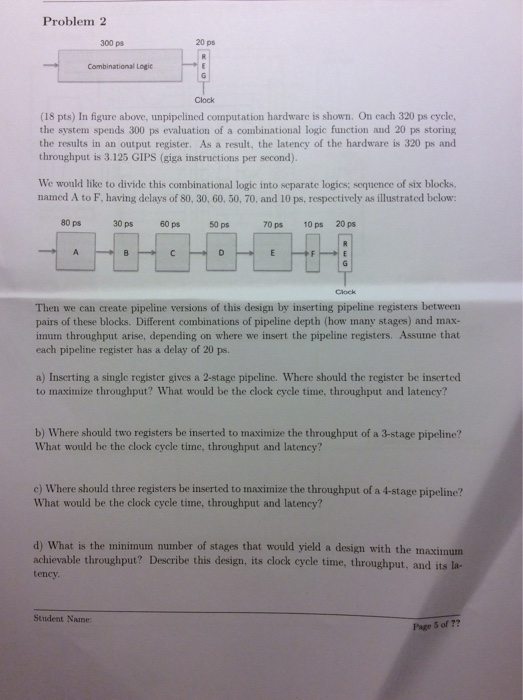
Problem 2 300 ps 20 ps Combinational Logic Clock (18 pts) In figure above, unpipelined computation hardware is shown. On cach 320 ps cycle, the system spends 300 ps evaluation of a combinational logic function and 20 ps storing the results in an output register. As a result, the latency of the hardware is 320 ps and throughput is 3.125 GIPS (giga instructions per second). We would like to divide this combinational logic into separate logics; sequence of six blocks. named A to F, having delays of 80, 30, 60. 50, 70, and 10 ps, respectively as illustrated below: 80 ps 30 ps 60 ps 50ps 70 ps 10 ps 20 ps Then we can create pipeline versions of this design by inserting pipeline registers between pairs of these blocks. Different combinations of pipeline depth (how many stages) and max- imun throughput arise, depending on where we insert the pipeline registers. Assune that each pipeline register has a delay of 20 ps. a) Inserting a single register gives a 2-stage pipeline. Where should the register be inserted to maximize throughput? What would be the clock cycle time, throughput and latency? b) Where should two registers be inserted to maximize the throughput of a 3-stage pipeline? What would be the clock cycle time, thronghput and latency? c) Where should three registers be inserted to maximize the throughput of a 4-stage pipeline? What would be the clock cycle time, throughput and latency? d) What is the minimun number of stages that would yield a design with the maximum achievable throughput? Describe this design, its clock cycle time, throughput, and its la- tency Student Nane Page 5 of
Step by Step Solution
There are 3 Steps involved in it

Get step-by-step solutions from verified subject matter experts