

Question: Problem 2. (35 Pts) The sketch below on the left shows a rectangular channel (gap = 2 8) through which an incompressible, Newtonian fluid flows
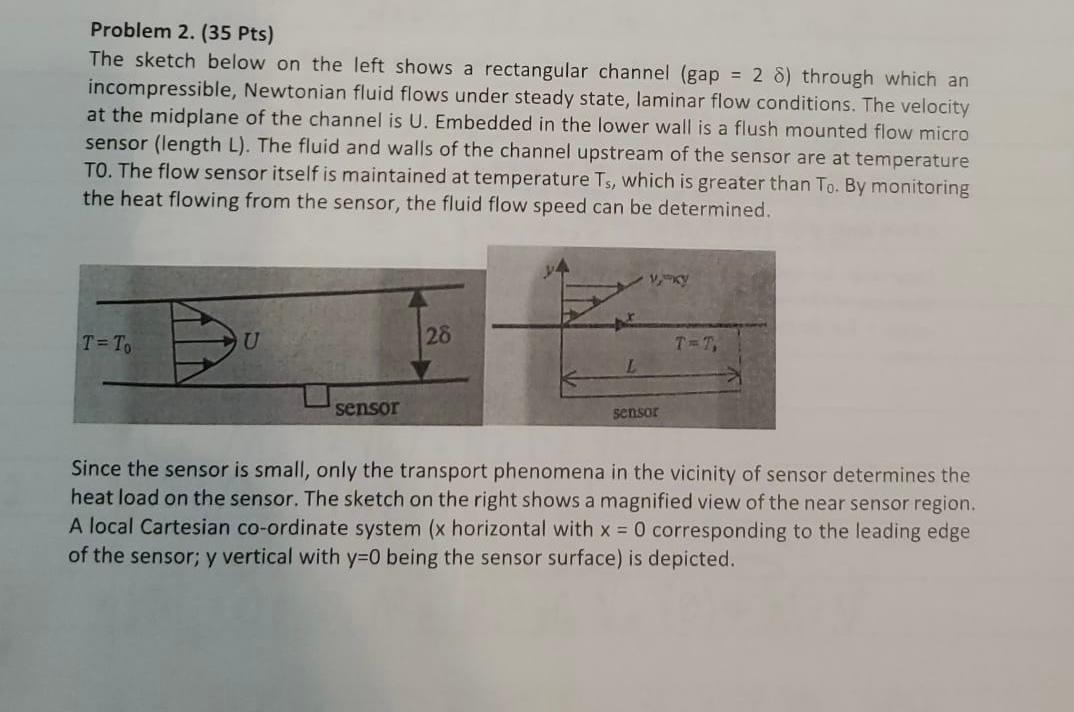
Problem 2. (35 Pts) The sketch below on the left shows a rectangular channel (gap = 2 8) through which an incompressible, Newtonian fluid flows under steady state, laminar flow conditions. The velocity at the midplane of the channel is U. Embedded in the lower wall is a flush mounted flow micro sensor (length L). The fluid and walls of the channel upstream of the sensor are at temperature TO. The flow sensor itself is maintained at temperature Ts, which is greater than To. By monitoring the heat flowing from the sensor, the fluid flow speed can be determined. T=To U 28 L sensor sensor Since the sensor is small, only the transport phenomena in the vicinity of sensor determines the heat load on the sensor. The sketch on the right shows a magnified view of the near sensor region. A local Cartesian co-ordinate system (x horizontal with x = 0 corresponding to the leading edge of the sensor; y vertical with y=0 being the sensor surface) is depicted. Problem 2. (35 Pts) The sketch below on the left shows a rectangular channel (gap = 2 8) through which an incompressible, Newtonian fluid flows under steady state, laminar flow conditions. The velocity at the midplane of the channel is U. Embedded in the lower wall is a flush mounted flow micro sensor (length L). The fluid and walls of the channel upstream of the sensor are at temperature TO. The flow sensor itself is maintained at temperature Ts, which is greater than To. By monitoring the heat flowing from the sensor, the fluid flow speed can be determined. T=To U 28 L sensor sensor Since the sensor is small, only the transport phenomena in the vicinity of sensor determines the heat load on the sensor. The sketch on the right shows a magnified view of the near sensor region. A local Cartesian co-ordinate system (x horizontal with x = 0 corresponding to the leading edge of the sensor; y vertical with y=0 being the sensor surface) is depicted
Step by Step Solution
There are 3 Steps involved in it

Get step-by-step solutions from verified subject matter experts