

Question: Problem 2: A single-piece bicycle crank is shown below under the following loading scenario: the rider is pedaling forward by applying a vertical force
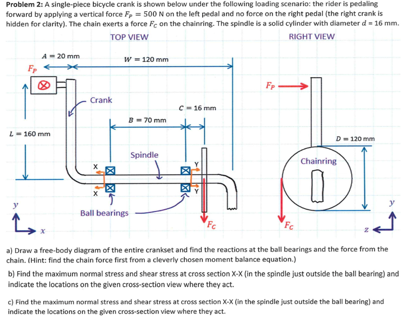
Problem 2: A single-piece bicycle crank is shown below under the following loading scenario: the rider is pedaling forward by applying a vertical force Fp = 500 N on the left pedal and no force on the right pedal (the right crank is hidden for clarity). The chain exerts a force Fc on the chainring. The spindle is a solid cylinder with diameter d = 16 mm. TOP VIEW RIGHT VIEW A = 20 mm FpX L = 160 mm y i Crank X X W = 120 mm B = 70 mm Ball bearings Spindle C = 16 mm Y FC Fp Fc D 120 mm Chainring 0 Z a) Draw a free-body diagram of the entire crankset and find the reactions at the ball bearings and the force from the chain. (Hint: find the chain force first from a cleverly chosen moment balance equation.) b) Find the maximum normal stress and shear stress at cross section X-X (in the spindle just outside the ball bearing) and indicate the locations on the given cross-section view where they act. c) Find the maximum normal stress and shear stress at cross section X-X (in the spindle just outside the ball bearing) and indicate the locations on the given cross-section view where they act.
Step by Step Solution
There are 3 Steps involved in it

Get step-by-step solutions from verified subject matter experts