

Question: Consider the brake pedal shown in Fig. (a) that is modelled as the leverimass system shown in Fig. b. The lever AOB is assumed
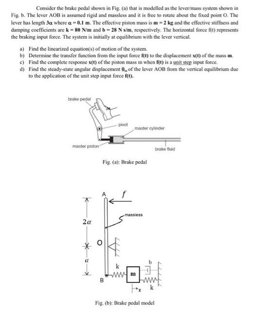
Consider the brake pedal shown in Fig. (a) that is modelled as the leverimass system shown in Fig. b. The lever AOB is assumed rigid and massless and it is free to rotate about the fixed point O. The lever has length 3a where a = 0.1 m. The effective piston mass is m= 2 kg and the effective stiffness and damping coefficients are k - 80 N/m and b = 28 N s/m, respectively. The horizontal force ft) represents the braking input force. The system is initially at equilibrium with the lever vertical. a) Find the linearized equation(s) of motion of the system. b) Determine the transfer function from the input force f(t) to the displacement x(t) of the mass m. c) Find the complete response x(t) of the piston mass m when f(t) is a unit step input force. d) Find the steady-state angular displacement 8, of the lever AOB from the vertical oquilibrium due to the application of the unit step input force fo. brake pedal pivot master cylinder master piston brake fuid Fig. (a): Brake pedal massiess 2a ww m Fig (b): Brake pedal model B.
Step by Step Solution
There are 3 Steps involved in it

Get step-by-step solutions from verified subject matter experts