

Question: PROBLEM 2 : Design a 4 - bar linkage with the left link represented as vector W and the right link as vector U to
PROBLEM : Design a bar linkage with the left link represented as vector and the right
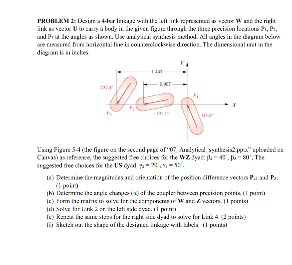
link as vector to carry a body in the given figure through the three precision locations
and at the angles as shown. Use analytical synthesis method. All angles in the diagram below
are measured from horizontal line in counterclockwise direction. The dimensional unit in the
diagram is in inches.
Using Figure the figure on the second page of Analyticalsynthesispptx uploaded on
Canvas as reference, the suggested free choices for the dyad: ; The
suggested free choices for the US dyad:
a Determine the magnitudes and orientation of the position difference vectors and
point
b Determine the angle changes of the coupler between precision points. point
c Form the matrix to solve for the components of and vectors. points
d Solve for Link on the left side dyad. point
e Repeat the same steps for the right side dyad to solve for Link points
f Sketch out the shape of the designed linkage with labels. pointsHow to solve
PROBLEM : Design a bar linkage with the left link represented as vector and the right
link as vector to carry a body in the given figure through the three precision locations
and at the angles as shown. Use analytical synthesis method. All angles in the diagram below
are measured from horizontal line in counterclockwise direction. The dimensional unit in the
diagram is in inches.
Using Figure the figure on the second page of Analyticalsynthesispptx uploaded on
Canvas as reference, the suggested free choices for the dyad: ; The
suggested free choices for the US dyad:
a Determine the magnitudes and orientation of the position difference vectors and
point
b Determine the angle changes of the coupler between precision points. point
c Form the matrix to solve for the components of and vectors. points
d Solve for Link on the left side dyad. point
e Repeat the same steps for the right side dyad to solve for Link points
f Sketch out the shape of the designed linkage with labels. points
Step by Step Solution
There are 3 Steps involved in it
1 Expert Approved Answer
Step: 1 Unlock

Question Has Been Solved by an Expert!
Get step-by-step solutions from verified subject matter experts
Step: 2 Unlock
Step: 3 Unlock