

Question: Problem 2 Problem 2 The lateral force resisting system for the restaurant in Problem 1 is located along line B - B in the plan
Problem Problem
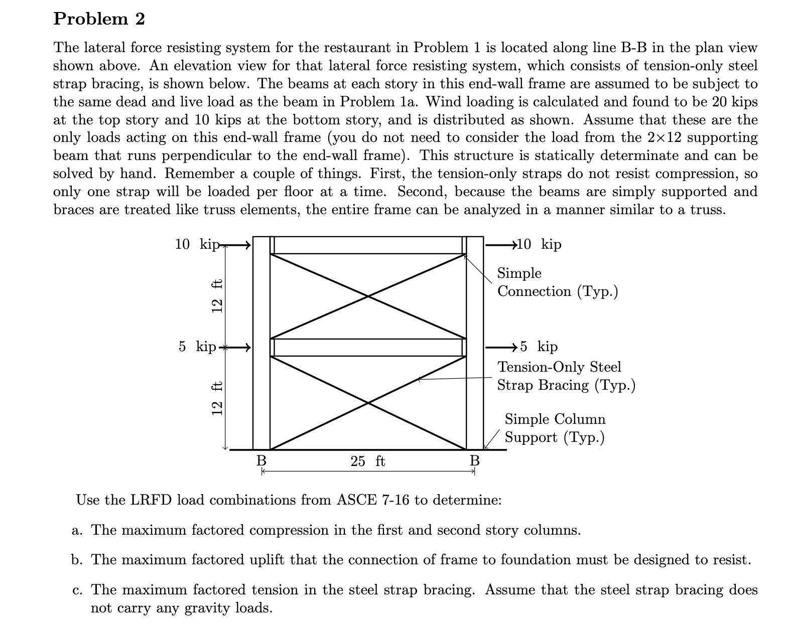
The lateral force resisting system for the restaurant in Problem is located along line BB in the plan view shown above. An elevation view for that lateral force resisting system, which consists of tensiononly steel strap bracing, is shown below. The beams at each story in this endwall frame are assumed to be subject to the same dead and live load as the beam in Problem a Wind loading is calculated and found to be kips at the top story and kips at the bottom story, and is distributed as shown. Assume that these are the only loads acting on this endwall frame you do not need to consider the load from the supporting beam that runs perpendicular to the endwall frame This structure is statically determinate and can be solved by hand. Remember a couple of things. First, the tensiononly straps do not resist compression, so only one strap will be loaded per floor at a time. Second, because the beams are simply supported and braces are treated like truss elements, the entire frame can be analyzed in a manner similar to a truss.
Use the LRFD load combinations from ASCE to determine:
a The maximum factored compression in the first and second story columns.
b The maximum factored uplift that the connection of frame to foundation must be designed to resist.
c The maximum factored tension in the steel strap bracing. Assume that the steel strap bracing does not carry any gravity loads.
The lateral force resisting system for the restaurant in Problem is located along line BB in the plan view
shown above. An elevation view for that lateral force resisting system, which consists of tensiononly steel
strap bracing, is shown below. The beams at each story in this endwall frame are assumed to be subject to
the same dead and live load as the beam in Problem a Wind loading is calculated and found to be kips
at the top story and kips at the bottom story, and is distributed as shown. Assume that these are the
only loads acting on this endwall frame you do not need to consider the load from the times supporting
beam that runs perpendicular to the endwall frame This structure is statically determinate and can be
solved by hand. Remember a couple of things. First, the tensiononly straps do not resist compression, so
only one strap will be loaded per floor at a time. Second, because the beams are simply supported and
braces are treated like truss elements, the entire frame can be analyzed in a manner similar to a truss.
ft
ft ft
B B
Simple
Connection Typ
Simple Column
Support Typ
TensionOnly Steel
Strap Bracing Typ
kip
kip
kip
kip
Use the LRFD load combinations from ASCE to determine:
a The maximum factored compression in the first and second story columns.
b The maximum factored uplift that the connection of frame to foundation must be designed to resist.
c The maximum factored tension in the steel strap bracing. Assume that the steel strap bracing does
not carry any gravity loads.
Step by Step Solution
There are 3 Steps involved in it
1 Expert Approved Answer
Step: 1 Unlock

Question Has Been Solved by an Expert!
Get step-by-step solutions from verified subject matter experts
Step: 2 Unlock
Step: 3 Unlock