

Question: Problem 2 : Push - Pull Power Amplifier ( 0 to 1 0 points ) 2 . 1 . Configure the circuit in Figure 2
Problem : PushPull Power Amplifier to points
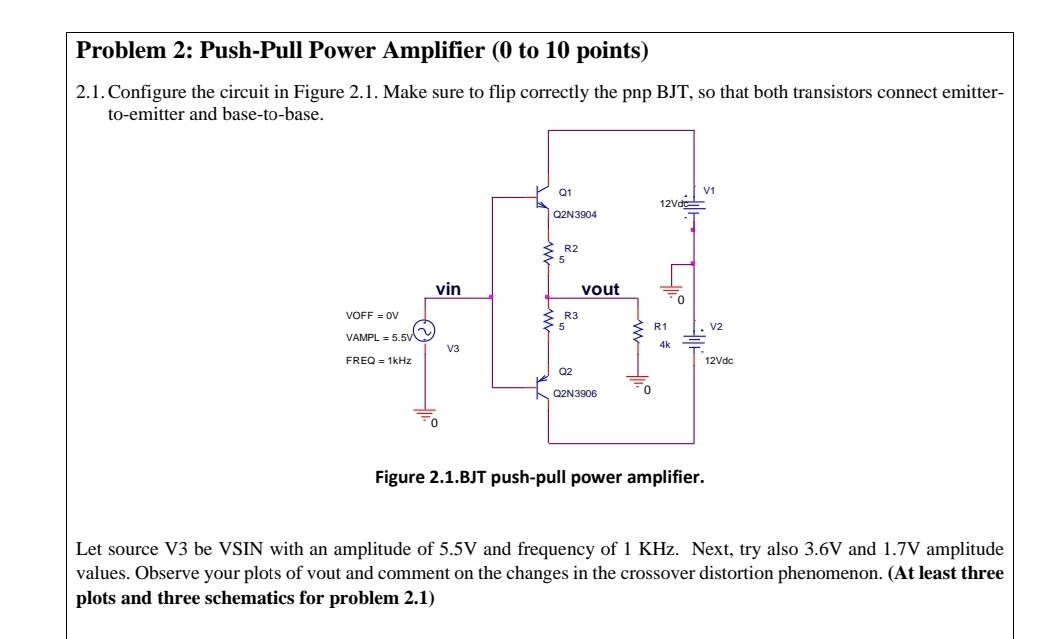
Configure the circuit in Figure Make sure to flip correctly the pnp BJT so that both transistors connect emittertoemitter and basetobase.
Figure BJT pushpull power amplitier.
Let source V be VSIN with an amplitude of V and frequency of KHz Next, try also V and V amplitude values. Observe your plots of vout and comment on the changes in the crossover distortion phenomenon. At least three plots and three schematics for problem
Step by Step Solution
There are 3 Steps involved in it
1 Expert Approved Answer
Step: 1 Unlock

Question Has Been Solved by an Expert!
Get step-by-step solutions from verified subject matter experts
Step: 2 Unlock
Step: 3 Unlock