

Question: Problem 3 ( 2 5 % ) Fig. 3 ( a ) shows a mechatronic system for moving the rack and pinion a motor. The
Problem
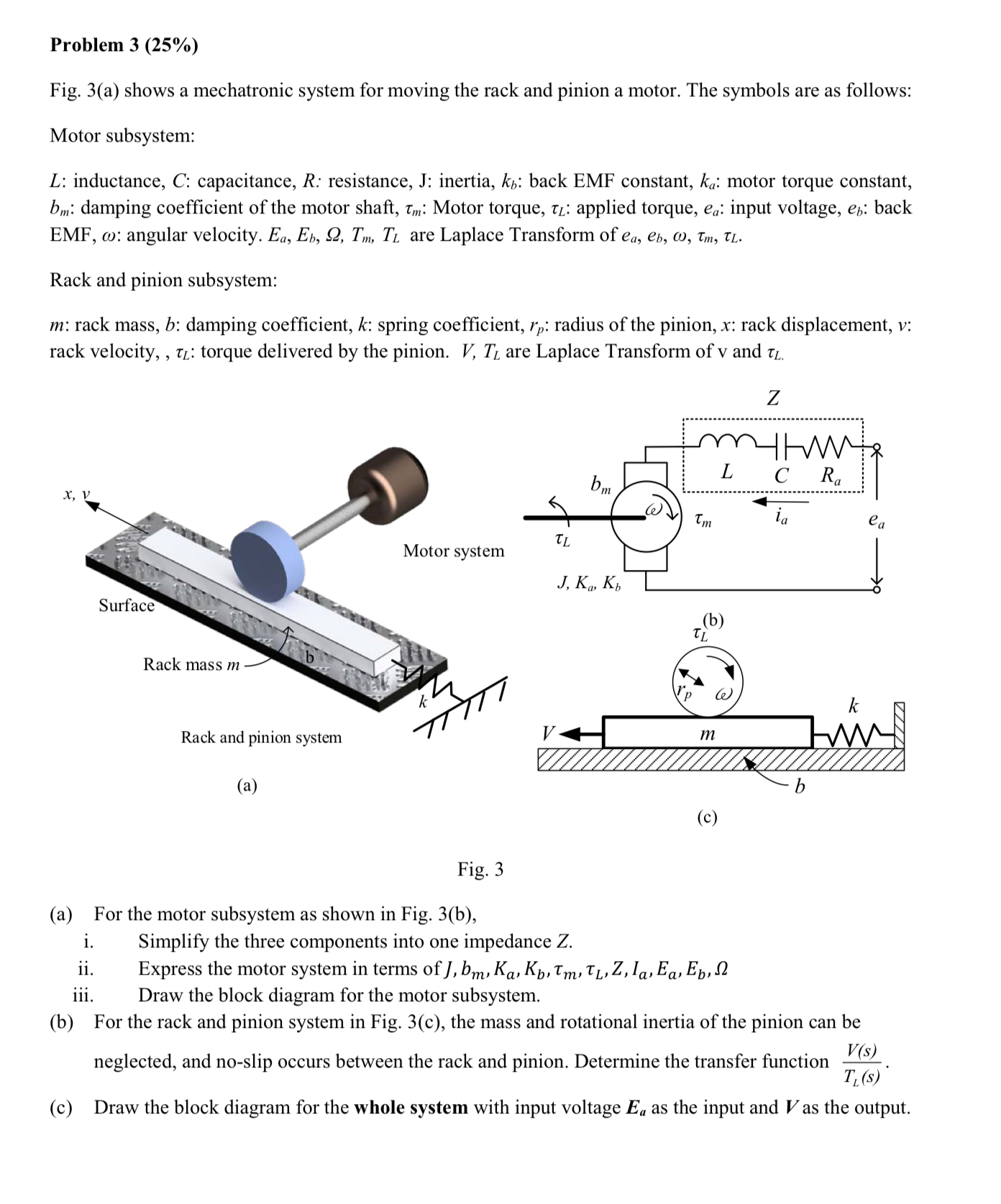
Fig. a shows a mechatronic system for moving the rack and pinion a motor. The symbols are as follows:
Motor subsystem:
: inductance, : capacitance, : resistance, J : inertia, : back EMF constant, : motor torque constant, : damping coefficient of the motor shaft, : Motor torque, : applied torque, : input voltage, : back EMF, : angular velocity. are Laplace Transform of
Rack and pinion subsystem:
: rack mass, : damping coefficient, : spring coefficient, : radius of the pinion, : rack displacement, : rack velocity,, : torque delivered by the pinion. are Laplace Transform of v and
Fig.
a For the motor subsystem as shown in Fig. b
i Simplify the three components into one impedance
ii Express the motor system in terms of
iii. Draw the block diagram for the motor subsystem.
b For the rack and pinion system in Fig. c the mass and rotational inertia of the pinion can be neglected, and noslip occurs between the rack and pinion. Determine the transfer function
c Draw the block diagram for the whole system with input voltage as the input and as the output.
Step by Step Solution
There are 3 Steps involved in it
1 Expert Approved Answer
Step: 1 Unlock

Question Has Been Solved by an Expert!
Get step-by-step solutions from verified subject matter experts
Step: 2 Unlock
Step: 3 Unlock