

Question: Problem 3 ( 4 5 points ) You are part of an engineering team tasked with creating a new channel to help transport post -
Problem points
You are part of an engineering team tasked with creating a new channel to help transport postrainfall runoff, known as stormwater. The existing stormwater channels have not been sufficient, leading to back flow and overflow, so you need to design a new stormwater channel that can bring the system back in to steady state during typical rain events.
Work through the steps below to determine A what typical flow rate the new channel must handle, B what the water depth of the new channel must be C what flow rate you would predict based on your design parameter choices, including error propagation, and D a short written interpretation of how your calculation in meets your system performance objective in including any speculation of future performance or conditions of concern, drawing on any realworld context you would like
Submit your responses to and as well as the detailed steps of your methods and rationale for decision making including screen shots, excel files, python files with comments, etc which are preferably in a different file.
System description
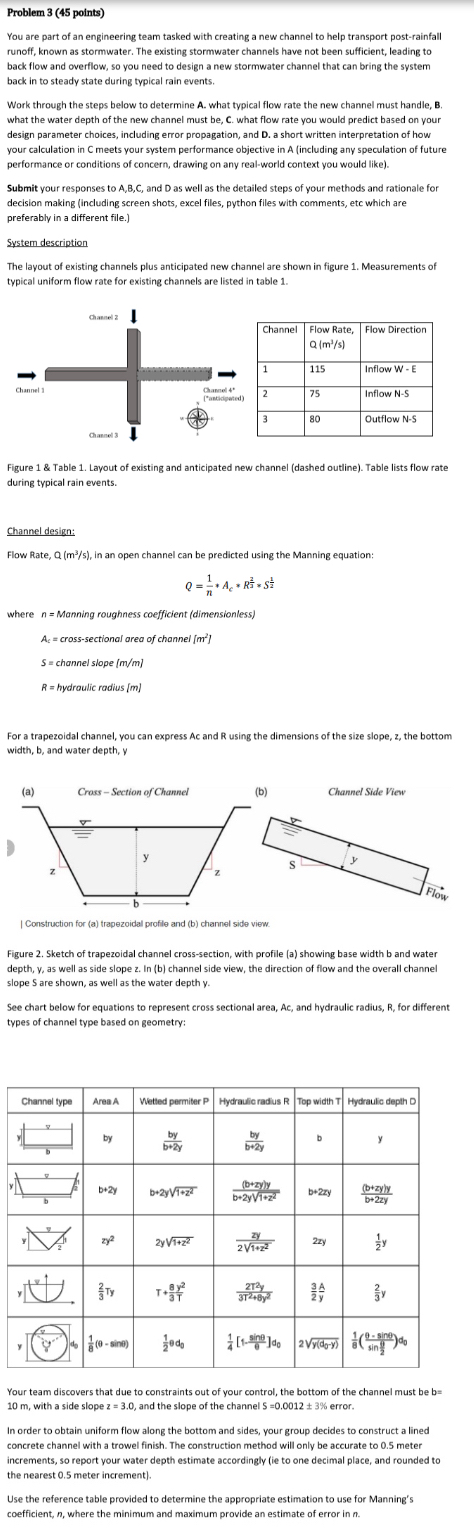
The layout of existing channels plus anticipated new channel are shown in figure Measurements of typical uniform flow rate for existing channels are listed in table
Figure & Table Layout of existing and anticipated new channel dashed outline Table lists flow rate during typical rain events.
Channel design:
Flow Rate, Q : in an open channel can be predicted using the Manning equation:
where Manning roughness coefficient dimensionless
crosssectional area of channel
channel slope
hydroulic radius
For a trapezoidal channel, you can express Ac and R using the dimensions of the size slope, z the bottom width, b and water depth,
Figure Sketch of trapezoidal channel crosssection, with profile a showing base width b and water depth, as well as side slope In b channel side view, the direction of flow and the overall channel slope are shown, as well as the water depth
See chart below for equations to represent cross sectional area, Ac and hydraulic radius, R for different types of channel type based on geometry:
tableChannel type,Area AWetted permiter Hydraulic radius RTop width THydraulic depth Dbyb
Step by Step Solution
There are 3 Steps involved in it
1 Expert Approved Answer
Step: 1 Unlock

Question Has Been Solved by an Expert!
Get step-by-step solutions from verified subject matter experts
Step: 2 Unlock
Step: 3 Unlock