

Question: Problem 3 Version 1 . The fully solid cylinder in Figure 2 is simply supported at points A and E and is manufactured with a
Problem
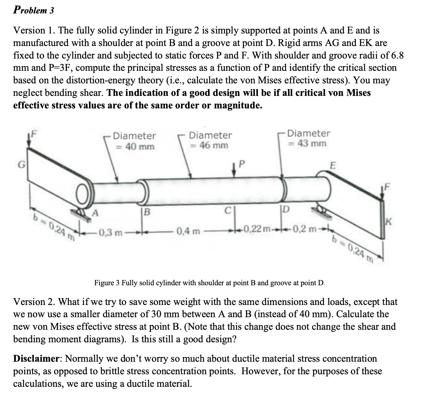
Version The fully solid cylinder in Figure is simply supported at points A and E and is manufactured with a shoulder at point B and a groove at point D Rigid arms AG and EK are fixed to the cylinder and subjected to static forces P and F With shoulder and groove radii of mm and compute the principal stresses as a function of P and identify the critical section based on the distortionenergy theory ie calculate the von Mises effective stress You may neglect bending shear. The indication of a good design will be if all critical von Mises effective stress values are of the same order or magnitude.
Figure Fully solid cylinder with shoulder at point B and groove at point D
Version What if we try to save some weight with the same dimensions and loads, except that we now use a smaller diameter of mm between A and B instead of mm Calculate the new von Mises effective stress at point BNote that this change does not change the shear and bending moment diagrams Is this still a good design?
Disclaimer: Normally we don't worry so much about ductile material stress concentration points, as opposed to brittle stress concentration points. However, for the purposes of these calculations, we are using a ductile material.
Step by Step Solution
There are 3 Steps involved in it
1 Expert Approved Answer
Step: 1 Unlock

Question Has Been Solved by an Expert!
Get step-by-step solutions from verified subject matter experts
Step: 2 Unlock
Step: 3 Unlock