

Question: Problem 3.9 Consider the L-shaped beam illustrated in Fig. 3.37. The beam is mounted to the wall at point A, the arm AB extends
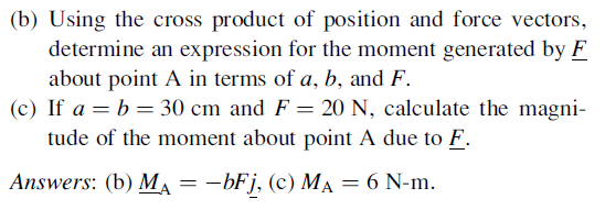
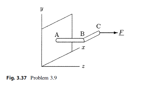
Problem 3.9 Consider the L-shaped beam illustrated in Fig. 3.37. The beam is mounted to the wall at point A, the arm AB extends in the z direction, and the arm BC extends in the x direction. A force F is applied in the z direction at the free-end of the beam. (a) If the lengths of arms AB and BC are a and b, respectively, and the magnitude of the applied force is F, observe that the position vector of point C relative to point A can be written as r= bi + ak and the force vector can be expressed as F = Fk, where i, j, and k are unit vectors indicating positive x, y, and z directions, respectively. (b) Using the cross product of position and force vectors, determine an expression for the moment generated by F about point A in terms of a, b, and F. (c) If a = b = 30 cm and F = 20 N, calculate the magni- tude of the moment about point A due to F. Answers: (b) M = bFj, (c) M = 6 N-m. MA A Fig. 3.37 Problem 3.9 B X .F
Step by Step Solution
3.51 Rating (161 Votes )
There are 3 Steps involved in it
To solve this problem we need to determine the moment about point A due to the force mathbfF Part b ... View full answer

Get step-by-step solutions from verified subject matter experts