

Question: Problem 4 . 6 3 The switch shown in Figure P 4 . 6 3 closes at t = 0 . Assume a DC steady
Problem
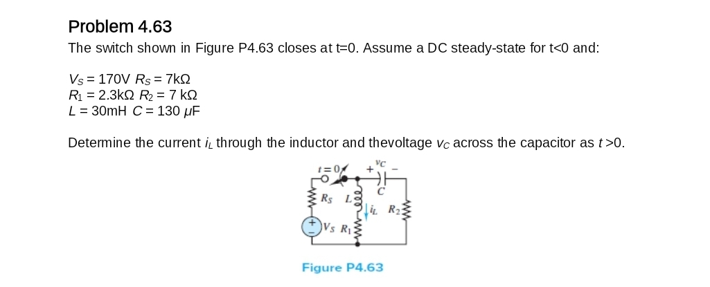
The switch shown in Figure P closes at Assume a DC steadystate for and:
Determine the current through the inductor and thevoltage across the capacitor as
Step by Step Solution
There are 3 Steps involved in it
1 Expert Approved Answer
Step: 1 Unlock

Question Has Been Solved by an Expert!
Get step-by-step solutions from verified subject matter experts
Step: 2 Unlock
Step: 3 Unlock