

Question: Problem 4 - State - space representations and graphs - systems with 2 - port elements The system shown below is a schematic representation of
Problem Statespace representations and graphs systems with port
elements
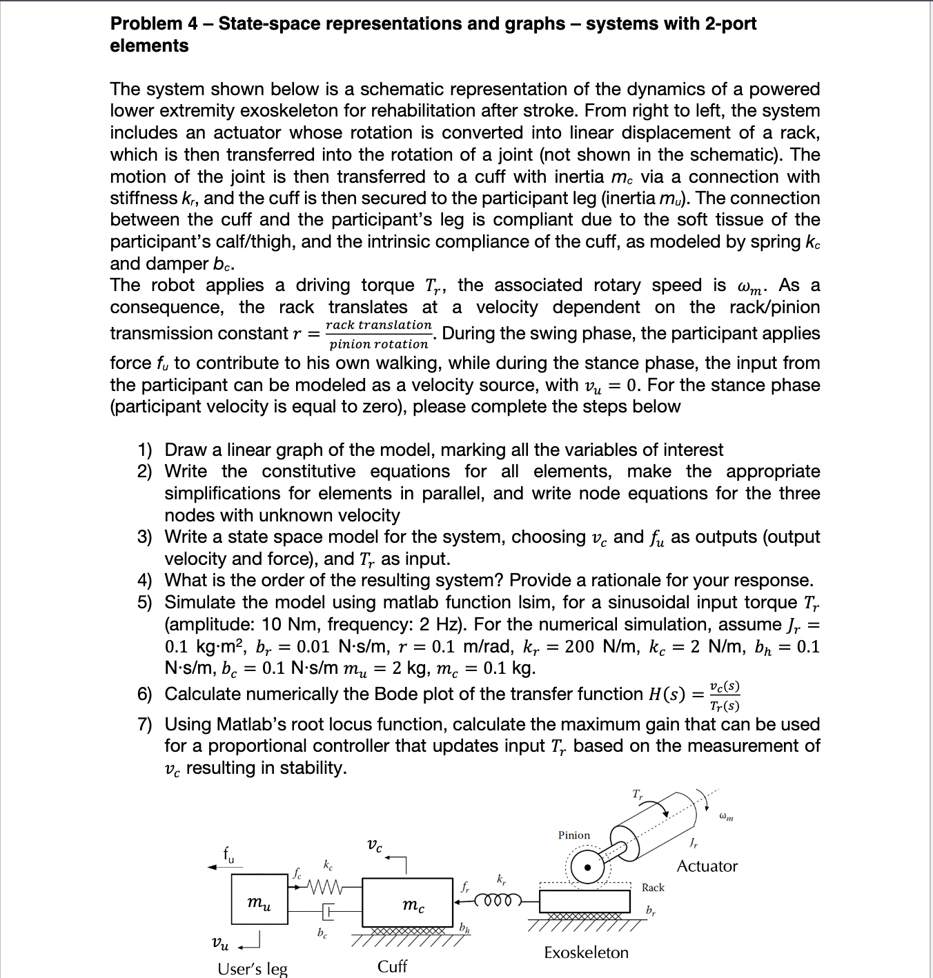
The system shown below is a schematic representation of the dynamics of a powered
lower extremity exoskeleton for rehabilitation after stroke. From right to left, the system
includes an actuator whose rotation is converted into linear displacement of a rack,
which is then transferred into the rotation of a joint not shown in the schematic The
motion of the joint is then transferred to a cuff with inertia via a connection with
stiffness and the cuff is then secured to the participant leg inertia The connection
between the cuff and the participant's leg is compliant due to the soft tissue of the
participant's calfthigh and the intrinsic compliance of the cuff, as modeled by spring
and damper
The robot applies a driving torque the associated rotary speed is As a
consequence, the rack translates at a velocity dependent on the rackpinion
transmission constant During the swing phase, the participant applies
force to contribute to his own walking, while during the stance phase, the input from
the participant can be modeled as a velocity source, with For the stance phase
participant velocity is equal to zero please complete the steps below
Draw a linear graph of the model, marking all the variables of interest
Write the constitutive equations for all elements, make the appropriate
simplifications for elements in parallel, and write node equations for the three
nodes with unknown velocity
Write a state space model for the system, choosing and as outputs output
velocity and force and as input.
What is the order of the resulting system? Provide a rationale for your response.
Simulate the model using matlab function Isim, for a sinusoidal input torque
amplitude: Nm frequency: Hz For the numerical simulation, assume
Calculate numerically the Bode plot of the transfer function
Using Matlab's root locus function, calculate the maximum gain that can be used
for a proportional controller that updates input based on the measurement of
resulting in stability.
Step by Step Solution
There are 3 Steps involved in it
1 Expert Approved Answer
Step: 1 Unlock

Question Has Been Solved by an Expert!
Get step-by-step solutions from verified subject matter experts
Step: 2 Unlock
Step: 3 Unlock