

Question: Problem 4 . Using a Decoder to represent a Boolean Equation ( 5 points ) For the following design problem, make a truth table that
Problem Using a Decoder to represent a Boolean Equation points
For the following design problem, make a truth table that describes the problem, then and
draw a logic diagram of the circuit you can draw the diagram by hand The circuit should use
a : Decoder with negated outputs low and any other logic gates: NOT, AND, OR NAND,
NOR, XOR. The logic gates in this design may have multibit inputs. A logical diagram should
contain block notations such as Full Adder, D FlipFlop, Decoder, Multiplexer and gate
symbols such as AND, OR and NOT
Hint : Which logic gate can we use to combine different outputs of the decoder into a single output?
Hint : Remember the logic value of an output of the decoder when it is "activated" or "chosen"
Check the answer from Problem
SOLVE: Design a logic circuit that will output HIGH when the input is an odd number less than
and an even number greater than or equal to and all inputs are smaller than The input should
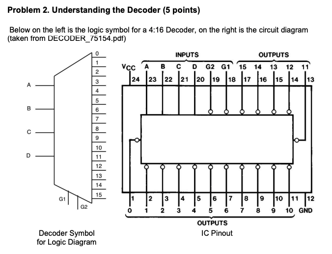
be a bit binary number. Design the circuit using a : decoder and other gates.Problem Understanding the Decoder points
Below on the left is the logic symbol for a : Decoder, on the right is the circuit diagram
taken from DECODERpdf
Decoder Symbol
for Logic Diagram
IC Pinout
Step by Step Solution
There are 3 Steps involved in it
1 Expert Approved Answer
Step: 1 Unlock

Question Has Been Solved by an Expert!
Get step-by-step solutions from verified subject matter experts
Step: 2 Unlock
Step: 3 Unlock