

Question: Problem 5 . 2 3 Consider the beam shown in ( Figure 1 ) . The roller at ( A ) and the
Problem
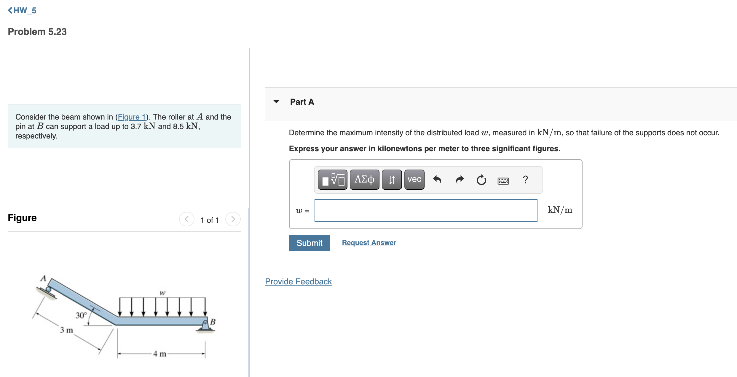
Consider the beam shown in Figure The roller at A and the pin at B can support a load up to kN and kN respectively.
Figure
Part A
Determine the maximum intensity of the distributed load w measured in mathrmkNmathrmm so that failure of the supports does not occur.
Express your answer in kilonewtons per meter to three significant figures.
w
mathrmkNmathrmm
Request Answer
Step by Step Solution
There are 3 Steps involved in it
1 Expert Approved Answer
Step: 1 Unlock

Question Has Been Solved by an Expert!
Get step-by-step solutions from verified subject matter experts
Step: 2 Unlock
Step: 3 Unlock