

Question: Problem 5 Consider the circuit shown in the diagram. The values of the components are: ( R = ) ( 4
Problem
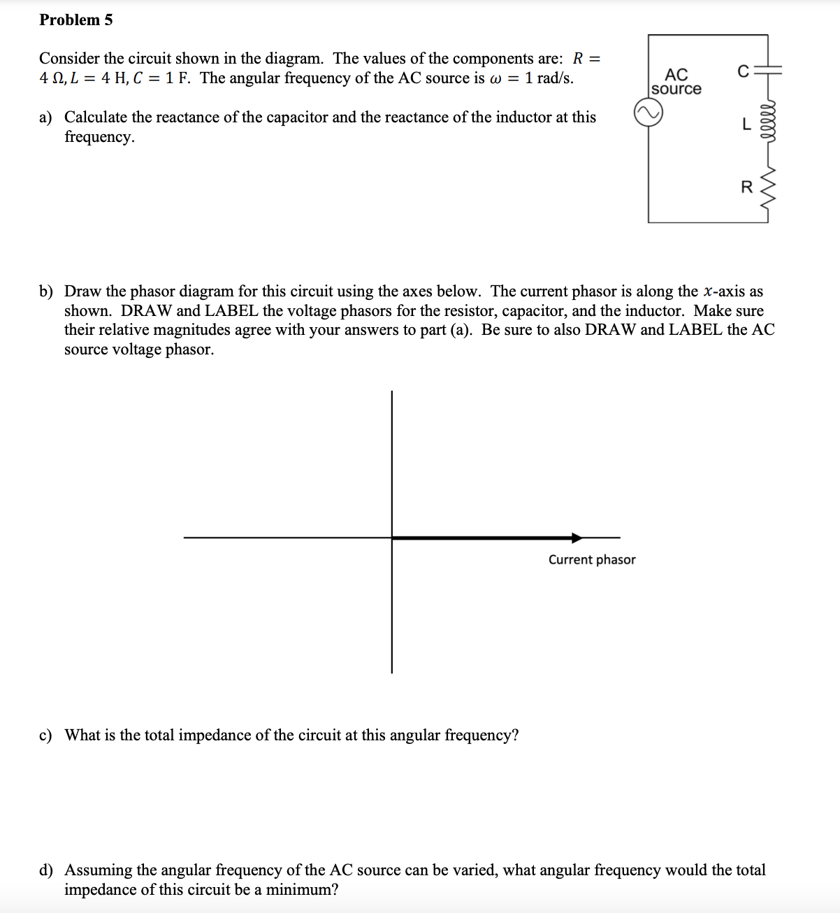
Consider the circuit shown in the diagram. The values of the components are: ROmega LmathrmH Cmathrm~F The angular frequency of the AC source is omegamathrmradmathrms
a Calculate the reactance of the capacitor and the reactance of the inductor at this frequency.
b Draw the phasor diagram for this circuit using the axes below. The current phasor is along the x axis as shown. DRAW and LABEL the voltage phasors for the resistor, capacitor, and the inductor. Make sure their relative magnitudes agree with your answers to part a Be sure to also DRAW and LABEL the AC source voltage phasor.
c What is the total impedance of the circuit at this angular frequency?
d Assuming the angular frequency of the AC source can be varied, what angular frequency would the total impedance of this circuit be a minimum?
Step by Step Solution
There are 3 Steps involved in it
1 Expert Approved Answer
Step: 1 Unlock

Question Has Been Solved by an Expert!
Get step-by-step solutions from verified subject matter experts
Step: 2 Unlock
Step: 3 Unlock