

Question: Problem 5 In Lab 7 you created a circuit to detect a heartbeat. The second stage of the circuit was, in fact, a filter designed
Problem
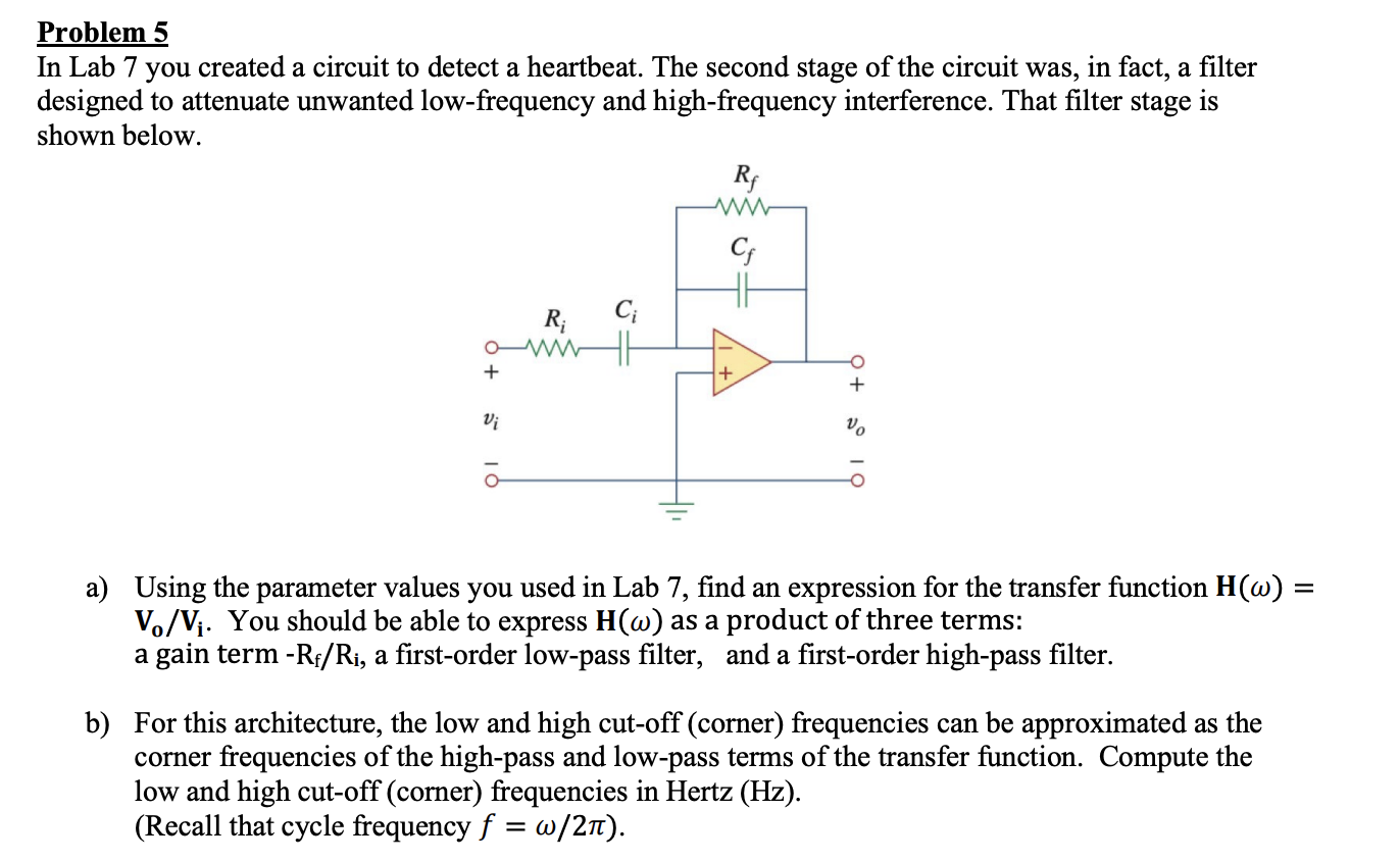
In Lab you created a circuit to detect a heartbeat. The second stage of the circuit was, in fact, a filter designed to attenuate unwanted lowfrequency and highfrequency interference. That filter stage is shown below.
a Using the parameter values you used in Lab find an expression for the transfer function mathbfHomegamathbfVmathbfmathbfVmathbfi You should be able to express mathbfHomega as a product of three terms: a gain term mathrmRmathrmfmathrmRmathrmi a firstorder lowpass filter, and a firstorder highpass filter.
b For this architecture, the low and high cutoff corner frequencies can be approximated as the corner frequencies of the highpass and lowpass terms of the transfer function. Compute the low and high cutoff corner frequencies in Hertz Hz
Recall that cycle frequency fomega pi
Step by Step Solution
There are 3 Steps involved in it
1 Expert Approved Answer
Step: 1 Unlock

Question Has Been Solved by an Expert!
Get step-by-step solutions from verified subject matter experts
Step: 2 Unlock
Step: 3 Unlock