

Question: Problem 5 . Rotor blade hub connection Figure. 3 shows a potential design for the attachment of a rotor blade to the rotorcraft hub. The
Problem Rotor blade hub connection
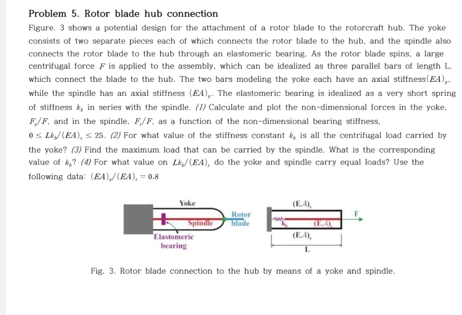
Figure. shows a potential design for the attachment of a rotor blade to the rotorcraft hub. The yoke
consists of two separate pieces each of which connects the rotor blade to the hub, and the spindle also
connects the rotor blade to the hub through an elastomeric bearing. As the rotor blade spins, a large
centrifugal force is applied to the assembly, which can be idealized as three parallel bars of length L
which connect the blade to the hub. The two bars modeling the yoke each have an axial stiffness
while the spindle has an axial stiffness The elastomeric bearing is idealized as a very short spring
of stiffness in series with the spindle. Calculate and plot the nondimensional forces in the yoke,
and in the spindle, as a function of the nondimensional bearing stiffness,
For what value of the stiffness constant is all the centrifugal load carried by
the yoke? Find the maximum load that can be carried by the spindle. What is the corresponding
value of For what value on do the yoke and spindle carry equal loads? Use the
following data:
Fig. Rotor blade connection to the hub by means of a yoke and spindle.
Step by Step Solution
There are 3 Steps involved in it
1 Expert Approved Answer
Step: 1 Unlock

Question Has Been Solved by an Expert!
Get step-by-step solutions from verified subject matter experts
Step: 2 Unlock
Step: 3 Unlock