

Question: Problem # 6 Schematic of a pump and piping system is given below. The pump is used to deliver hot water at 1 4 0
Problem #
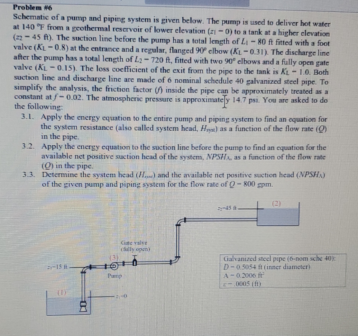
Schematic of a pump and piping system is given below. The pump is used to deliver hot water at from a geothermal reservoir of lower elevation to a tank at a higher elevation The suction line before the pump has a total length of fitted with a foot valve at the entrance and a regular, flanged elbow The discharge line after the pump has a total length of fitted with two elbows and a fully open gate valve The loss coefficient of the exit from the pipe to the tank is Both suction line and discharge line are made of nominal schedule galvanized steel pipe. To simplify the analysis, the friction factor inside the pipe can be approximately treated as a constant at The atmospheric pressure is approximatey psi. You are asked to do the following:
Apply the energy equation to the entire pump and piping system to find an cquation for the system resistance also called system head, as a function of the flow rate in the pipe.
Apply the energy equation to the suction line before the pump to find an equation for the available net positive suction head of the system, as a function of the flow rate in the pipe.
Determine the system head and the available net positive suction head NPSHA of the given pump and piping system for the flow rate of
Step by Step Solution
There are 3 Steps involved in it
1 Expert Approved Answer
Step: 1 Unlock

Question Has Been Solved by an Expert!
Get step-by-step solutions from verified subject matter experts
Step: 2 Unlock
Step: 3 Unlock