

Question: PROBLEM 7 - 10.13.6 mm, following instructions below, not the book's Draw object in SolidWorks. Set up a four-view display in third-angle projection (front /
PROBLEM 7 - 10.13.6 mm, following instructions below, not the book's
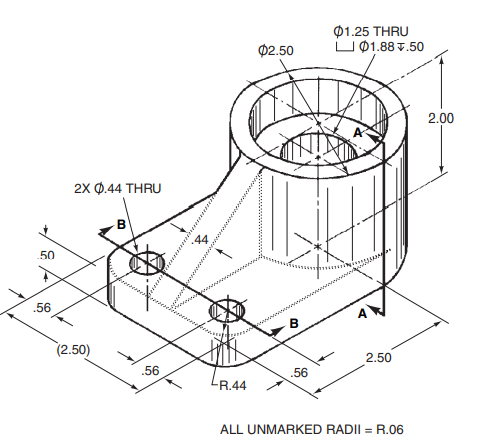
Draw object in SolidWorks. Set up a four-view display in third-angle projection (front / top / right / tri) and do a screen capturelook for the Four View option under the View Orientation controls (heads-up toolbar, top center of screen). You'll notice as you model the part that the horizontal, 10 mm holes intersect the R12 trough, even though that's not what's seen in the book pictorial. This is yet another small error in the book.
NOTE: you are doing a screen capture while in SW part mode, as opposed to creating an actual SW drawing.
01.25 THRU U 01.88 7.50 02.50 2.00 2x 0.44 THRU B 14 50 .56 B (2.50) 2.50 .56 .56 R.44 ALL UNMARKED RADII = R.06 01.25 THRU U 01.88 7.50 02.50 2.00 2x 0.44 THRU B 14 50 .56 B (2.50) 2.50 .56 .56 R.44 ALL UNMARKED RADII = R.06
Step by Step Solution
There are 3 Steps involved in it

Get step-by-step solutions from verified subject matter experts