

Question: Problem 7 In the table given on the next page the symbols const_val, equate_val, and var_val are defined according to the ARM Assembler directives EQU,
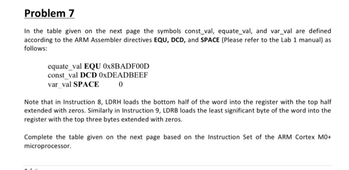
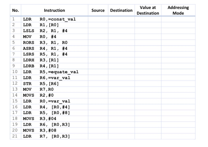
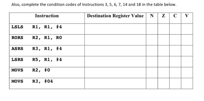
Problem 7 In the table given on the next page the symbols const_val, equate_val, and var_val are defined according to the ARM Assembler directives EQU, DCD, and SPACE (Please refer to the Lab 1 manual) as follows: equate val EQU OX8BADFOOD const val DCD OXDEADBEEF var val SPACE 0 Note that in Instruction 8, LDRH loads the bottom half of the word into the register with the top half extended with zeros. Similarly in Instruction 9, LDRB loads the least significant byte of the word into the register with the top three bytes extended with zeros. Complete the table given on the next page based on the Instruction Set of the ARM Cortex MO+ microprocessor No. Instruction Source Value at Destination Destination Addressing Mode 1 LDR RO, =const_val 2 LDR R1, [RO] LSLS R2, R1, #4 MOV RO, #4 RORS R3, R1, RO ASRS R4, R1, #4 LSRS R5, R1, #4 8 LDRH R3, (R1] LDRB R4, [R1] 10 LDR R5, Eequate_val 11 LDR R6, Evar_val 12 STR R5, [R6] 13 MOV R7, RO 14 MOVS R2, #0 15 LDR RO, var_val 16 LDR R4, [RO, #4] 17 LDR R5, [RO, #8] 18 MOVS R3, #04 19 LDR R6, [RO, R3] 20 MOVS R3, #08 21 LDR R7, [RO, R3] Also, complete the condition codes of Instructions 3, 5, 6, 7, 14 and 18 in the table below. Instruction Destination Register Value N Z LSLS R1, R1, #4 RORS R2, R1, RO ASRS R3, R1, #4 LSRS R5, R1, #4 MOVS R2, #0 MOVS R3, #04 Problem 7 In the table given on the next page the symbols const_val, equate_val, and var_val are defined according to the ARM Assembler directives EQU, DCD, and SPACE (Please refer to the Lab 1 manual) as follows: equate val EQU OX8BADFOOD const val DCD OXDEADBEEF var val SPACE 0 Note that in Instruction 8, LDRH loads the bottom half of the word into the register with the top half extended with zeros. Similarly in Instruction 9, LDRB loads the least significant byte of the word into the register with the top three bytes extended with zeros. Complete the table given on the next page based on the Instruction Set of the ARM Cortex MO+ microprocessor No. Instruction Source Value at Destination Destination Addressing Mode 1 LDR RO, =const_val 2 LDR R1, [RO] LSLS R2, R1, #4 MOV RO, #4 RORS R3, R1, RO ASRS R4, R1, #4 LSRS R5, R1, #4 8 LDRH R3, (R1] LDRB R4, [R1] 10 LDR R5, Eequate_val 11 LDR R6, Evar_val 12 STR R5, [R6] 13 MOV R7, RO 14 MOVS R2, #0 15 LDR RO, var_val 16 LDR R4, [RO, #4] 17 LDR R5, [RO, #8] 18 MOVS R3, #04 19 LDR R6, [RO, R3] 20 MOVS R3, #08 21 LDR R7, [RO, R3] Also, complete the condition codes of Instructions 3, 5, 6, 7, 14 and 18 in the table below. Instruction Destination Register Value N Z LSLS R1, R1, #4 RORS R2, R1, RO ASRS R3, R1, #4 LSRS R5, R1, #4 MOVS R2, #0 MOVS R3, #04
Step by Step Solution
There are 3 Steps involved in it

Get step-by-step solutions from verified subject matter experts