

Question: Problem 7 Problem 7 . The stiffness matrix for the frame depicted below is to be determined, with degrees of freedom depicted as numbers next
Problem
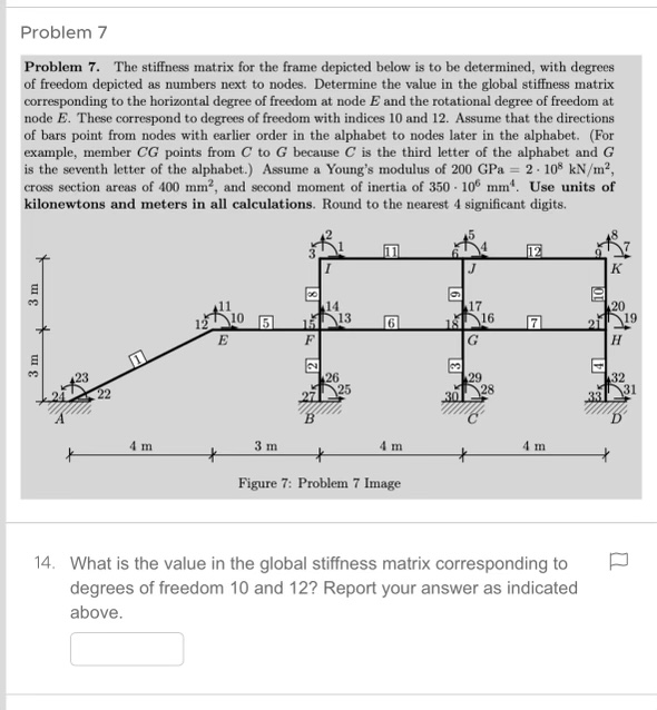
Problem The stiffness matrix for the frame depicted below is to be determined, with degrees of freedom depicted as numbers next to nodes. Determine the value in the global stiffness matrix corresponding to the horizontal degree of freedom at node and the rotational degree of freedom at node These correspond to degrees of freedom with indices and Assume that the directions of bars point from nodes with earlier order in the alphabet to nodes later in the alphabet. For example, member points from to because is the third letter of the alphabet and is the seventh letter of the alphabet. Assume a Young's modulus of GPa cross section areas of and second moment of inertia of Use units of kilonewtons and meters in all calculations. Round to the nearest significant digits.
What is the value in the global stiffness matrix corresponding to degrees of freedom and Report your answer as indicated above.
Step by Step Solution
There are 3 Steps involved in it
1 Expert Approved Answer
Step: 1 Unlock

Question Has Been Solved by an Expert!
Get step-by-step solutions from verified subject matter experts
Step: 2 Unlock
Step: 3 Unlock