

Problem 9 (50 Points) An air-cooled aluminum heat sink is used to keep electronics cool (see...
Fantastic news! We've Found the answer you've been seeking!
Question:
Transcribed Image Text:
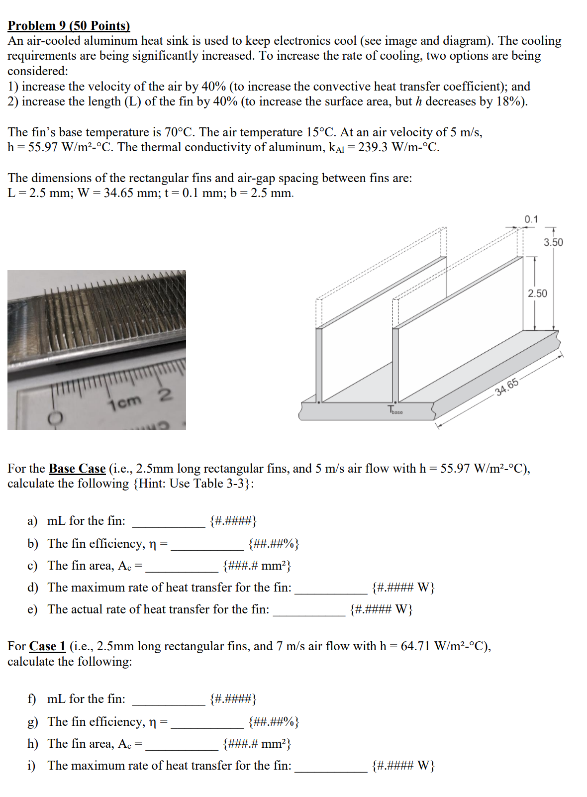
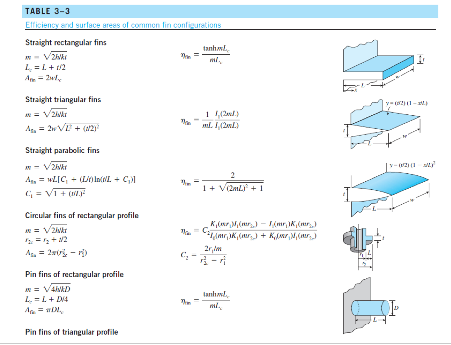
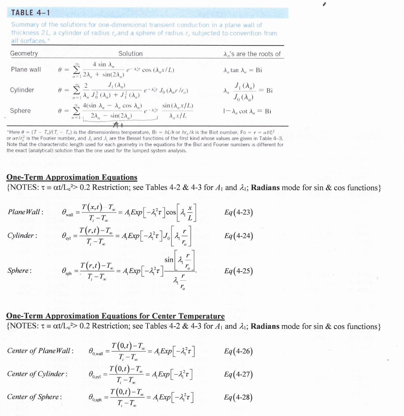
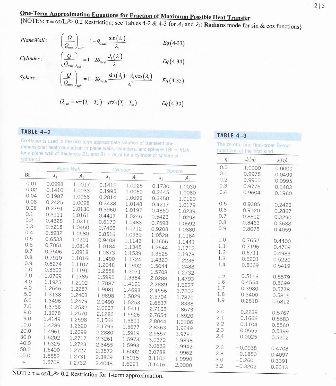
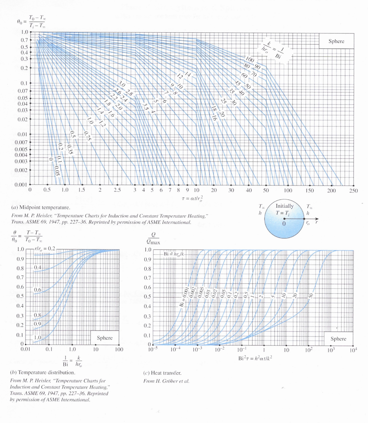
Problem 9 (50 Points) An air-cooled aluminum heat sink is used to keep electronics cool (see image and diagram). The cooling requirements are being significantly increased. To increase the rate of cooling, two options are being considered: 1) increase the velocity of the air by 40% (to increase the convective heat transfer coefficient); and 2) increase the length (L) of the fin by 40% (to increase the surface area, but h decreases by 18%). The fin's base temperature is 70C. The air temperature 15C. At an air velocity of 5 m/s, h=55.97 W/m-C. The thermal conductivity of aluminum, k = 239.3 W/m-C. The dimensions of the rectangular fins and air-gap spacing between fins are: L = 2.5 mm; W = 34.65 mm; t = 0.1 mm; b = 2.5 mm. 1cm 2 Tease 34.65 For the Base Case (i.e., 2.5mm long rectangular fins, and 5 m/s air flow with h = 55.97 W/m-C), calculate the following {Hint: Use Table 3-3}: a) mL for the fin: {#.####} b) The fin efficiency, n = {##.##%} c) The fin area, Ac =. {###.# mm} d) The maximum rate of heat transfer for the fin: {#.#### W} e) The actual rate of heat transfer for the fin: {#.#### W} For Case 1 (i.e., 2.5mm long rectangular fins, and 7 m/s air flow with h = 64.71 W/m-C), calculate the following: f) mL for the fin: {#.####} g) The fin efficiency, n = {##.##%} h) The fin area, Ac = {###.# mm} i) The maximum rate of heat transfer for the fin: {#.#### W} 0.1 3.50 2.50 j) The actual rate of heat transfer for the fin: {#.#### W} k) The increase in the actual rate of heat transfer (i.e., (J - E)/E *100): For Case 2 (i.e., 3.5mm long rectangular fins, and 5 m/s air flow with h = 47.30 W/m-C), calculate the following: 1) mL for the fin: {##.##%} {#.####} m) The fin efficiency, n = {##.##%} n) The fin area, Ac =. {###.# mm} o) The maximum rate of heat transfer for the fin: p) The actual rate of heat transfer for the fin: {#.#### W} {#.#### W} q) The increase in the actual rate of heat transfer (i.e., (P - E)/E *100): Based on your analysis which method yields the better increase in cooling capacity? Case 1: Increase the air flow through the fin array. Case 2: Increase the length of the fins to increase heat transfer surface area (even though h went down by 18%). {##.##%} TABLE 3-3 Efficiency and surface areas of common fin configurations Straight rectangular fins m = V2h/kt L = L + 1/2 tanhmL nfin = mL Afin = 2wLc Straight triangular fins m = V2h/kt y= (1/2) (1-x/L) nfin Afin = 2w L + (t/2) 1 I(2mL) mL I(2mL) w Straight parabolic fins y = (t/2) (1 - x/L) m = V2hlkt 2 Afin = WL[C + (L/t) In(t/L + C)] nfin 1 + V (2mL) + 1 t C = 1 + (1/L) Circular fins of rectangular profile m = V2h/kt 12c = 12 + 1/2 Afin = 2 (1-1) Pin fins of rectangular profile m = 4h/kD L = L+D/4 Afin = DLC Pin fins of triangular profile K(mr)I(mr) I(mr)K(mr2) 21(mr)K(mr) + K(mr)I(mr) nfin = C 2r/m C = tanhmL = Mfin mLc 12 Pin fins of triangular profile 2 I(2mL) nfin mL I(2mL) 12(x) = 10 (x) - (2/x)I (x) where x = 2mL y = (D/2) (1-x/L) 2 1 + (2mL/3) + 1 m = 4h/kD D = 1 + (D/2) 2 Afin Pin fins of parabolic profile m = 4h/kD L Aim = TDIC,C4 - In(2DC /L + C)] An 8D C3 = 1 + 2(D/L) C = 1 + (DIL) 2D Pin fins of parabolic profile (blunt tip) m = 4h/kD Afin = D4 961 {[16(L/D) + 1]/2 nfin 2- 1} nfin = 3 12(4mL/3) 2mL 10(4mL/3) y= (D/2) (1-x/L) y = (D/2) (1-x/L)1/2 TABLE 4-1 Summary of the solutions for one-dimensional transient conduction in a plane wall of thickness 2L, a cylinder of radius r, and a sphere of radius r. subjected to convention from all surfaces.* A's are the roots of Geometry Solution 4 sin A, Plane wall 0 = e-cos (Ax/L) A,, tan A,, = Bi 2A + sin(2A) 2 J(AR) J(A) Cylinder 0 = e-Jo (Arr) = Bi A J (A) + J} (A) Jo (Am) 4(sin A - A cos ) Sphere 0 = e-== 2A, sin (A,,x/L) Ax/L 1-A,, cot A, Bi sin(2A) AL *Here @ (TT)/(TT) is the dimensionless temperature, BihL/k or hr, /k is the Biot number, Fo= T = at/L or ar/r2 is the Fourier number, and Jo and J are the Bessel functions of the first kind whose values are given in Table 4-3. Note that the characteristic length used for each geometry in the equations for the Biot and Fourier numbers is different for the exact (analytical) solution than the one used for the lumped system analysis. One-Term Approximation Equations {NOTES: = at/Lc2> 0.2 Restriction; see Tables 4-2 & 4-3 for A and 21; Radians mode for sin & cos functions} Plane Wall: 0. = T(x,t)-Tx wall T-T = A,Exp[-]cos ]00[4] Eq(4-23) Cylinder: Ocvl = T(r,t)-T T-T = 4, Exp [1}t] J [1, Eq(4-24) r sin T(r.)-T-A Exp[-] Sphere: sph T-T Eq(4-25) r ro One-Term Approximation Equations for Center Temperature {NOTES: t = at/Lc> 0.2 Restriction; see Tables 4-2 & 4-3 for 41 and 21; Radians mode for sin & cos functions} Center of Plane Wall: Center of Cylinder: Center of Sphere: T(0.1)-T = AExp[-] Eq(4-26) 00,wall T-T T(0,1)-T = A Exp[-x+] Eq(4-27) 00,cyl T-T T(0,t)-T AExp[-2] Eq(4-28) 00,sph T-T One-Term Approximation Equations for Fraction of Maximum Possible Heat Transfer {NOTES: Tat/Le2> 0.2 Restriction; see Tables 4-2 & 4-3 for A and 21; Radians mode for sin & cos functions} sin() 215 Q Plane Wall: =1-00,wall Eq(4-33) Qmax wall Q J(2) Cylinder: =1-200.cyl Eq(4-34) max cyl Q Sphere: =1-30 0,sphi Qmax sin()- cos(4) 23 Eq (4-35) sph 2max =mc(T-T)= pvc (T-T) Eq (4-30) TABLE 4-2 Coefficients used in the one-term approximate solution of transient one- dimensional heat conduction in plane walls, cylinders, and spheres (Bi = huk for a plane wall of thickness 2L, and Bi=hrolk for a cylinder or sphere of radius ro) TABLE 4-3 The zeroth- and first-order Bessel functions of the first kind n Jo(n) J(n) 0.0 1.0000 0.0000 Plane Wall Cylinder Sphere 0.1 Bi A 0.01 0.0998 1.0017 0.02 0.1410 1.0033 0.04 0.1987 1.0066 0.06 0.2425 1.0098 0.08 0.2791 1.0130 A A 0.1412 1.0025 0.1730 0.1995 1.0050 0.2445 A 0.2 1.0030 0.3 1.0060 0.4 7234 0.9975 0.0499 0.9900 0.0995 0.9776 0.1483 0.9604 0.1960 0.2814 1.0099 0.3450 1.0120 0.3438 1.0148 0.4217 0.5 1.0179 0.9385 0.2423 0.3960 1.0197 0.4860 1.0239 0.6 0.9120 0.2867 0.1 0.3111 1.0161 0.4417 1.0246 0.5423 1.0298 0.7 0.8812 0.3290 0.2 0.4328 1.0311 0.6170 1.0483 0.7593 1.0592 0.8 0.8463 0.3688 0.3 0.5218 1.0450 0.7465 1.0712 0.9208 1.0880 0.9 0.8075 0.4059 0.4 0.5932 1.0580 0.8516 1.0931 1.0528 1.1164 0.5 0.6533 1.0701 0.9408 1.0 1.1143 0.7652 0.4400 1.1656 1.1441 0.6 0.7051 1.0814 1.0184 1.1 1.1345 0.7196 1.2644 1.1713 0.4709 0.7 0.7506 1.0918 1.2 1.0873 0.6711 1.1539 1.3525 1.1978 0.4983 0.8 0.7910 1.1016 1.3 1.1490 0.6201 1.1724 0.5220 0.9 0.8274 1.1107 1.2048 1.0 0.8603 1.1191 1.2558 2.0 1.0769 1.1785 1.5995 1.4320 1.1902 1.5044 1.2488 1.2071 1.5708 1.2732 1.3384 2.0288 1.2236 1.4 0.5669 0.5419 1.5 0.5118 0.5579 1.4793 1.6 0.4554 0.5699 3.0 1.1925 1.2102 1.7887 1.4191 2.2889 1.6227 1.7 0.3980 0.5778 4.0 1.2646 1.2287 1.9081 1.4698 2.4556 1.7202 1.8 0.3400 0.5815 5.0 1.3138 1.2403 1.9898 1.5029 2.5704 1.7870 1.9 0.2818 0.5812 6.0 1.3496 1.2479 2.0490 1.5253 2.6537 1.8338 7.0 1.3766 1.2532 2.0937 1.5411 2.7165 1.8673 2.0 0.2239 0.5767 8.0 1.3978 1.2570 2.1286 1.5526 2.7654 1.8920 2.1 0.1666 0.5683 9.0 1.4149 1.2598 2.1566 1.5611 2.8044 1.9106 2.2 0.1104 0.5560 10.0 1.4289 1.2620 2.1795 1.5677 2.8363 1.9249 2.3 0.0555 0.5399 20.0 1.4961 1.2699 2.2880 30.0 1.5202 1.2717 2.3261 40.0 50.0 100.0 00 1.5919 1.5973 3.0372 1.9898 1.5325 1.2723 2.3455 1.5993 3.0632 1.9942 1.5400 1.2727 2.3572 1.6002 3.0788 1.9962 1.5552 1.2731 2.3809 1.6015 3.1102 1.5708 1.2732 2.4048 1.6021 3.1416 2.9857 1.9781 2.4 0.0025 0.5202 2.6 -0.0968 0.4708 2.8 -0.1850 0.4097 1.9990 3.0 -0.2601 0.3391 2.0000 3.2 -0.3202 0.2613 NOTE: Tat/L> 0.2 Restriction for 1-term approximation. To-Tx 00 = T-T 1.0 0.7 0.5+ 0.4+ 0.3 0.2 0.1 0.07 0.05 0.04 0.03 1.0 0.7 0.5 0.8 0.6: 6 14 k 1 hL Bi 10 9 8 25 100 90 80 ++70 60 45-50 35 40' Plate 0.02 20.4 S 8 0.01 18.30 0.007 0.005 0.004 0.003 0.002 1 0.001 0 1 2 3 46810 14 18 22 26 30 50 70 100 120 150 300 400 500 600 700 T = t/L (a) Midplane temperature. From M. P. Heisler, "Temperature Charts for Induction and Constant Temperature Heating," Trans. ASME 69, 1947, pp. 227-36. Reprinted by permission of ASME International. Tx Initially T h T = Ti h 0 L 1 2L # == 80 T-T To-Tx 1.0 x/L = 0.2 Qmax 1.0 0.9 0.9 Bi=hL/k 0.4 0.8 0.8 0.7 0.7 0.6 0.6 0.6 0.5 0.5 0.002: 0.4 0.8 0.4 0.3 0.3 0.9 0.2 0.2 0.1 1.0 0.1 Plate 0 Plate 0 0.01 0.1 1.0 10 100 10-5 10-4 10-3 10-2 10-1 1 10 102 103 10+ 1 k Bir = hatlk = Bi hL (b) Temperature distribution. From M. P. Heisler, "Temperature Charts for Induction and Constant Temperature Heating," Trans. ASME 69, 1947, pp. 227-36. Reprinted by permission of ASME International. (c) Heat transfer. From H. Grber et al. To-Tx T-T% 00 = 1.0 0.7 0.5 0.4 0.3 0.2 0.1 0.07 0.05 0.04 0.03 0.02 0.01 0.007 0.005 0.004 0.003 0.002 3.5 2.5 1.8 1.42 1.0 1.6 0 e Bi hro 100 90 70-80. 50 40 60 45 25 20 18 16. 14. 12 10 30 Cylinder 0.001 0 1 2 3 46810 14 18 22 26 30 50 70 100 120 140 150 250 350 T = atir (a) Centerline temperature. From M. P. Heisler, "Temperature Charts for Induction and Constant Temperature Heating," Trans. ASME 69, 1947, pp. 227-36. Reprinted by permission of ASME International. h T Initially T T=T h 0 ro T-Tx = 80 To-T% Qmax 1.0 rlr=0.2 1.0 Bi=hrlk 0.9 0.9 10.4 0.8 0.8 0.7 0.7 0.6 -0.6- 0.6 0.5 0.5 100'0 = 0.002 .005 0.01 B 0.4 0.4 0.8 0.3 0.3 0.2 -0.9 0.2 0.1 = 0.1 1.0 Cylinder Cylinder 0 0 0.01 0.1 1.0 10 100 10-5 10-4 10-3 10-2 10-1 1 10 10 103 10+ 1 k Bir=hatlk = Bi hro (b) Temperature distribution. From M. P. Heisler, "Temperature Charts for Induction and Constant Temperature Heating," Trans. ASME 69, 1947, pp. 227-36. Reprinted by permission of ASME International. (c) Heat transfer. From H. Grber et al. 80= 1.0 To-Tx T-T 0.7 0.5 0.4 0.3 0.2 0.1 0.07 0.05 0.04 0.03 0.02 1.0 3.0 2.8 2.6 2.4 2.2 2.0 1.8 A 1.6 k hro - Bi 100 90 80 70 60 50 45 40 35 14 30 Sphere 0.01 0.007 0.005 0.004 0.003 0.002 5 0.001 0 0.5 1.0 1.5 2 2.5 3 4 5 6 78 9 10 20 30 40 50 100 150 200 250 T = atr (a) Midpoint temperature. From M. P. Heisler, "Temperature Charts for Induction and Constant Temperature Heating," Trans. ASME 69, 1947, pp. 227-36. Reprinted by permission of ASME International. Tx h Initially T=T Tx h 0 % r Q Qmax 1.0 Bi=hrolk 0.9 0.8 0.7 0.6 0.5 - 12 | 0.4 B 0.3 0.2 0.1 Sphere 0. 100 10-5 10-4 10-3 10-2 10-1 1 10 10 103 10+ Bir=hat/k T-T = 00 To-Tx 1.0 rlr = 0.2 0.9 0.8 -0.4. 0.7 0.6 0.6 0.5 0.4 0.3 0.8 0.2 0.9 0.1 1.0 0 0.01 0.1 1.0 10 1 = Bi k hr Sphere (b) Temperature distribution. From M. P. Heisler, "Temperature Charts for Induction and Constant Temperature Heating," Trans. ASME 69, 1947, pp. 227-36. Reprinted by permission of ASME International. (c) Heat transfer. From H. Grber et al. Problem 9 (50 Points) An air-cooled aluminum heat sink is used to keep electronics cool (see image and diagram). The cooling requirements are being significantly increased. To increase the rate of cooling, two options are being considered: 1) increase the velocity of the air by 40% (to increase the convective heat transfer coefficient); and 2) increase the length (L) of the fin by 40% (to increase the surface area, but h decreases by 18%). The fin's base temperature is 70C. The air temperature 15C. At an air velocity of 5 m/s, h=55.97 W/m-C. The thermal conductivity of aluminum, k = 239.3 W/m-C. The dimensions of the rectangular fins and air-gap spacing between fins are: L = 2.5 mm; W = 34.65 mm; t = 0.1 mm; b = 2.5 mm. 1cm 2 Tease 34.65 For the Base Case (i.e., 2.5mm long rectangular fins, and 5 m/s air flow with h = 55.97 W/m-C), calculate the following {Hint: Use Table 3-3}: a) mL for the fin: {#.####} b) The fin efficiency, n = {##.##%} c) The fin area, Ac =. {###.# mm} d) The maximum rate of heat transfer for the fin: {#.#### W} e) The actual rate of heat transfer for the fin: {#.#### W} For Case 1 (i.e., 2.5mm long rectangular fins, and 7 m/s air flow with h = 64.71 W/m-C), calculate the following: f) mL for the fin: {#.####} g) The fin efficiency, n = {##.##%} h) The fin area, Ac = {###.# mm} i) The maximum rate of heat transfer for the fin: {#.#### W} 0.1 3.50 2.50 j) The actual rate of heat transfer for the fin: {#.#### W} k) The increase in the actual rate of heat transfer (i.e., (J - E)/E *100): For Case 2 (i.e., 3.5mm long rectangular fins, and 5 m/s air flow with h = 47.30 W/m-C), calculate the following: 1) mL for the fin: {##.##%} {#.####} m) The fin efficiency, n = {##.##%} n) The fin area, Ac =. {###.# mm} o) The maximum rate of heat transfer for the fin: p) The actual rate of heat transfer for the fin: {#.#### W} {#.#### W} q) The increase in the actual rate of heat transfer (i.e., (P - E)/E *100): Based on your analysis which method yields the better increase in cooling capacity? Case 1: Increase the air flow through the fin array. Case 2: Increase the length of the fins to increase heat transfer surface area (even though h went down by 18%). {##.##%} TABLE 3-3 Efficiency and surface areas of common fin configurations Straight rectangular fins m = V2h/kt L = L + 1/2 tanhmL nfin = mL Afin = 2wLc Straight triangular fins m = V2h/kt y= (1/2) (1-x/L) nfin Afin = 2w L + (t/2) 1 I(2mL) mL I(2mL) w Straight parabolic fins y = (t/2) (1 - x/L) m = V2hlkt 2 Afin = WL[C + (L/t) In(t/L + C)] nfin 1 + V (2mL) + 1 t C = 1 + (1/L) Circular fins of rectangular profile m = V2h/kt 12c = 12 + 1/2 Afin = 2 (1-1) Pin fins of rectangular profile m = 4h/kD L = L+D/4 Afin = DLC Pin fins of triangular profile K(mr)I(mr) I(mr)K(mr2) 21(mr)K(mr) + K(mr)I(mr) nfin = C 2r/m C = tanhmL = Mfin mLc 12 Pin fins of triangular profile 2 I(2mL) nfin mL I(2mL) 12(x) = 10 (x) - (2/x)I (x) where x = 2mL y = (D/2) (1-x/L) 2 1 + (2mL/3) + 1 m = 4h/kD D = 1 + (D/2) 2 Afin Pin fins of parabolic profile m = 4h/kD L Aim = TDIC,C4 - In(2DC /L + C)] An 8D C3 = 1 + 2(D/L) C = 1 + (DIL) 2D Pin fins of parabolic profile (blunt tip) m = 4h/kD Afin = D4 961 {[16(L/D) + 1]/2 nfin 2- 1} nfin = 3 12(4mL/3) 2mL 10(4mL/3) y= (D/2) (1-x/L) y = (D/2) (1-x/L)1/2 TABLE 4-1 Summary of the solutions for one-dimensional transient conduction in a plane wall of thickness 2L, a cylinder of radius r, and a sphere of radius r. subjected to convention from all surfaces.* A's are the roots of Geometry Solution 4 sin A, Plane wall 0 = e-cos (Ax/L) A,, tan A,, = Bi 2A + sin(2A) 2 J(AR) J(A) Cylinder 0 = e-Jo (Arr) = Bi A J (A) + J} (A) Jo (Am) 4(sin A - A cos ) Sphere 0 = e-== 2A, sin (A,,x/L) Ax/L 1-A,, cot A, Bi sin(2A) AL *Here @ (TT)/(TT) is the dimensionless temperature, BihL/k or hr, /k is the Biot number, Fo= T = at/L or ar/r2 is the Fourier number, and Jo and J are the Bessel functions of the first kind whose values are given in Table 4-3. Note that the characteristic length used for each geometry in the equations for the Biot and Fourier numbers is different for the exact (analytical) solution than the one used for the lumped system analysis. One-Term Approximation Equations {NOTES: = at/Lc2> 0.2 Restriction; see Tables 4-2 & 4-3 for A and 21; Radians mode for sin & cos functions} Plane Wall: 0. = T(x,t)-Tx wall T-T = A,Exp[-]cos ]00[4] Eq(4-23) Cylinder: Ocvl = T(r,t)-T T-T = 4, Exp [1}t] J [1, Eq(4-24) r sin T(r.)-T-A Exp[-] Sphere: sph T-T Eq(4-25) r ro One-Term Approximation Equations for Center Temperature {NOTES: t = at/Lc> 0.2 Restriction; see Tables 4-2 & 4-3 for 41 and 21; Radians mode for sin & cos functions} Center of Plane Wall: Center of Cylinder: Center of Sphere: T(0.1)-T = AExp[-] Eq(4-26) 00,wall T-T T(0,1)-T = A Exp[-x+] Eq(4-27) 00,cyl T-T T(0,t)-T AExp[-2] Eq(4-28) 00,sph T-T One-Term Approximation Equations for Fraction of Maximum Possible Heat Transfer {NOTES: Tat/Le2> 0.2 Restriction; see Tables 4-2 & 4-3 for A and 21; Radians mode for sin & cos functions} sin() 215 Q Plane Wall: =1-00,wall Eq(4-33) Qmax wall Q J(2) Cylinder: =1-200.cyl Eq(4-34) max cyl Q Sphere: =1-30 0,sphi Qmax sin()- cos(4) 23 Eq (4-35) sph 2max =mc(T-T)= pvc (T-T) Eq (4-30) TABLE 4-2 Coefficients used in the one-term approximate solution of transient one- dimensional heat conduction in plane walls, cylinders, and spheres (Bi = huk for a plane wall of thickness 2L, and Bi=hrolk for a cylinder or sphere of radius ro) TABLE 4-3 The zeroth- and first-order Bessel functions of the first kind n Jo(n) J(n) 0.0 1.0000 0.0000 Plane Wall Cylinder Sphere 0.1 Bi A 0.01 0.0998 1.0017 0.02 0.1410 1.0033 0.04 0.1987 1.0066 0.06 0.2425 1.0098 0.08 0.2791 1.0130 A A 0.1412 1.0025 0.1730 0.1995 1.0050 0.2445 A 0.2 1.0030 0.3 1.0060 0.4 7234 0.9975 0.0499 0.9900 0.0995 0.9776 0.1483 0.9604 0.1960 0.2814 1.0099 0.3450 1.0120 0.3438 1.0148 0.4217 0.5 1.0179 0.9385 0.2423 0.3960 1.0197 0.4860 1.0239 0.6 0.9120 0.2867 0.1 0.3111 1.0161 0.4417 1.0246 0.5423 1.0298 0.7 0.8812 0.3290 0.2 0.4328 1.0311 0.6170 1.0483 0.7593 1.0592 0.8 0.8463 0.3688 0.3 0.5218 1.0450 0.7465 1.0712 0.9208 1.0880 0.9 0.8075 0.4059 0.4 0.5932 1.0580 0.8516 1.0931 1.0528 1.1164 0.5 0.6533 1.0701 0.9408 1.0 1.1143 0.7652 0.4400 1.1656 1.1441 0.6 0.7051 1.0814 1.0184 1.1 1.1345 0.7196 1.2644 1.1713 0.4709 0.7 0.7506 1.0918 1.2 1.0873 0.6711 1.1539 1.3525 1.1978 0.4983 0.8 0.7910 1.1016 1.3 1.1490 0.6201 1.1724 0.5220 0.9 0.8274 1.1107 1.2048 1.0 0.8603 1.1191 1.2558 2.0 1.0769 1.1785 1.5995 1.4320 1.1902 1.5044 1.2488 1.2071 1.5708 1.2732 1.3384 2.0288 1.2236 1.4 0.5669 0.5419 1.5 0.5118 0.5579 1.4793 1.6 0.4554 0.5699 3.0 1.1925 1.2102 1.7887 1.4191 2.2889 1.6227 1.7 0.3980 0.5778 4.0 1.2646 1.2287 1.9081 1.4698 2.4556 1.7202 1.8 0.3400 0.5815 5.0 1.3138 1.2403 1.9898 1.5029 2.5704 1.7870 1.9 0.2818 0.5812 6.0 1.3496 1.2479 2.0490 1.5253 2.6537 1.8338 7.0 1.3766 1.2532 2.0937 1.5411 2.7165 1.8673 2.0 0.2239 0.5767 8.0 1.3978 1.2570 2.1286 1.5526 2.7654 1.8920 2.1 0.1666 0.5683 9.0 1.4149 1.2598 2.1566 1.5611 2.8044 1.9106 2.2 0.1104 0.5560 10.0 1.4289 1.2620 2.1795 1.5677 2.8363 1.9249 2.3 0.0555 0.5399 20.0 1.4961 1.2699 2.2880 30.0 1.5202 1.2717 2.3261 40.0 50.0 100.0 00 1.5919 1.5973 3.0372 1.9898 1.5325 1.2723 2.3455 1.5993 3.0632 1.9942 1.5400 1.2727 2.3572 1.6002 3.0788 1.9962 1.5552 1.2731 2.3809 1.6015 3.1102 1.5708 1.2732 2.4048 1.6021 3.1416 2.9857 1.9781 2.4 0.0025 0.5202 2.6 -0.0968 0.4708 2.8 -0.1850 0.4097 1.9990 3.0 -0.2601 0.3391 2.0000 3.2 -0.3202 0.2613 NOTE: Tat/L> 0.2 Restriction for 1-term approximation. To-Tx 00 = T-T 1.0 0.7 0.5+ 0.4+ 0.3 0.2 0.1 0.07 0.05 0.04 0.03 1.0 0.7 0.5 0.8 0.6: 6 14 k 1 hL Bi 10 9 8 25 100 90 80 ++70 60 45-50 35 40' Plate 0.02 20.4 S 8 0.01 18.30 0.007 0.005 0.004 0.003 0.002 1 0.001 0 1 2 3 46810 14 18 22 26 30 50 70 100 120 150 300 400 500 600 700 T = t/L (a) Midplane temperature. From M. P. Heisler, "Temperature Charts for Induction and Constant Temperature Heating," Trans. ASME 69, 1947, pp. 227-36. Reprinted by permission of ASME International. Tx Initially T h T = Ti h 0 L 1 2L # == 80 T-T To-Tx 1.0 x/L = 0.2 Qmax 1.0 0.9 0.9 Bi=hL/k 0.4 0.8 0.8 0.7 0.7 0.6 0.6 0.6 0.5 0.5 0.002: 0.4 0.8 0.4 0.3 0.3 0.9 0.2 0.2 0.1 1.0 0.1 Plate 0 Plate 0 0.01 0.1 1.0 10 100 10-5 10-4 10-3 10-2 10-1 1 10 102 103 10+ 1 k Bir = hatlk = Bi hL (b) Temperature distribution. From M. P. Heisler, "Temperature Charts for Induction and Constant Temperature Heating," Trans. ASME 69, 1947, pp. 227-36. Reprinted by permission of ASME International. (c) Heat transfer. From H. Grber et al. To-Tx T-T% 00 = 1.0 0.7 0.5 0.4 0.3 0.2 0.1 0.07 0.05 0.04 0.03 0.02 0.01 0.007 0.005 0.004 0.003 0.002 3.5 2.5 1.8 1.42 1.0 1.6 0 e Bi hro 100 90 70-80. 50 40 60 45 25 20 18 16. 14. 12 10 30 Cylinder 0.001 0 1 2 3 46810 14 18 22 26 30 50 70 100 120 140 150 250 350 T = atir (a) Centerline temperature. From M. P. Heisler, "Temperature Charts for Induction and Constant Temperature Heating," Trans. ASME 69, 1947, pp. 227-36. Reprinted by permission of ASME International. h T Initially T T=T h 0 ro T-Tx = 80 To-T% Qmax 1.0 rlr=0.2 1.0 Bi=hrlk 0.9 0.9 10.4 0.8 0.8 0.7 0.7 0.6 -0.6- 0.6 0.5 0.5 100'0 = 0.002 .005 0.01 B 0.4 0.4 0.8 0.3 0.3 0.2 -0.9 0.2 0.1 = 0.1 1.0 Cylinder Cylinder 0 0 0.01 0.1 1.0 10 100 10-5 10-4 10-3 10-2 10-1 1 10 10 103 10+ 1 k Bir=hatlk = Bi hro (b) Temperature distribution. From M. P. Heisler, "Temperature Charts for Induction and Constant Temperature Heating," Trans. ASME 69, 1947, pp. 227-36. Reprinted by permission of ASME International. (c) Heat transfer. From H. Grber et al. 80= 1.0 To-Tx T-T 0.7 0.5 0.4 0.3 0.2 0.1 0.07 0.05 0.04 0.03 0.02 1.0 3.0 2.8 2.6 2.4 2.2 2.0 1.8 A 1.6 k hro - Bi 100 90 80 70 60 50 45 40 35 14 30 Sphere 0.01 0.007 0.005 0.004 0.003 0.002 5 0.001 0 0.5 1.0 1.5 2 2.5 3 4 5 6 78 9 10 20 30 40 50 100 150 200 250 T = atr (a) Midpoint temperature. From M. P. Heisler, "Temperature Charts for Induction and Constant Temperature Heating," Trans. ASME 69, 1947, pp. 227-36. Reprinted by permission of ASME International. Tx h Initially T=T Tx h 0 % r Q Qmax 1.0 Bi=hrolk 0.9 0.8 0.7 0.6 0.5 - 12 | 0.4 B 0.3 0.2 0.1 Sphere 0. 100 10-5 10-4 10-3 10-2 10-1 1 10 10 103 10+ Bir=hat/k T-T = 00 To-Tx 1.0 rlr = 0.2 0.9 0.8 -0.4. 0.7 0.6 0.6 0.5 0.4 0.3 0.8 0.2 0.9 0.1 1.0 0 0.01 0.1 1.0 10 1 = Bi k hr Sphere (b) Temperature distribution. From M. P. Heisler, "Temperature Charts for Induction and Constant Temperature Heating," Trans. ASME 69, 1947, pp. 227-36. Reprinted by permission of ASME International. (c) Heat transfer. From H. Grber et al.
Expert Answer:

Related Book For 
Thermodynamics An Engineering Approach
ISBN: 978-0073398174
8th edition
Authors: Yunus A. Cengel, Michael A. Boles
Posted Date:
Students also viewed these mechanical engineering questions
-
The following additional information is available for the Dr. Ivan and Irene Incisor family from Chapters 1-5. Ivan's grandfather died and left a portfolio of municipal bonds. In 2012, they pay Ivan...
-
This assignment requires you to complete the 2022 tax reporting for a fictional woman named Anna Smith. Question 1 T1 - step 4 - line 66 This is Anna's taxable income Answer: Question 2 T1 - step...
-
In the year to 5 April 2021, Thomas More made the following disposals: (i) A flat in a house that he had purchased on 1 December 2010 for 80,000. It had never been occupied as the main residence and...
-
The liquid octane in a gas turbine is burned with 400% excess air that enters the combustion chamber at 7 8C. The products of combustion leave the constant-pressure combustion chamber at 707 8C. The...
-
Ringgold Corporation has outstanding at December 31, 2022, 50,000 shares of $20 par value, cumulative, 6% preferred stock and 200,000 shares of $5 par value common stock. All shares were outstanding...
-
Juliette Shulof Furs (JSF) was a New York corporation that had been in the fur-dealing business for 15 years. George Shulof, an officer of JSF, attended two auctions conducted by Finnish Fur Sales...
-
Juhn and Sons Wholesale Fruit Distributors employ one worker whose job is to load fruit on outgoing company trucks. Trucks arrive at the loading gate at an average of 24 per day, or 3 per hour,...
-
A Joe plays football for his high school team. He is 17 years old, 6 feet tall and weighs 180 pounds. His coach has recommended that he gain 10 pounds over the next six months, but not at the expense...
-
Huayi Compressor Barcelona, S.L. was founded in 2013 when Huayi Group (Huayi), a Chinese state-owned enterprise, acquired Cubigel Compressors, S.A., a bankrupt Spanish industrial enterprise. While...
-
What other advantages can BCM gain from partnering with EMAs, NGOs, and other business continuity professionals? What other activities in one phase affect activities in another? In addition to RA and...
-
The domain of f(x) = 2 arcsin(2-e') is
-
Evaluate C4 and 11P 4.
-
1) The CEO would like to see higher sales and a forecasted net income of $250,000. Assume that operating costs (excluding depreciation) will remain at 55% of sales, depreciation expense will increase...
-
Nvidia, one of the world's largest semiconductor companies that manufacture microchips, reported earnings per share in 2021 of $3.95, and paid dividends per share of $0.68. Its earnings were expected...
-
A CPA conducts an audit on a company's financial statements and finds that the statements are materially correct and are in compliance with gaap without reservations or exception. What form of...
-
Problem 3.5 (4 points). We will prove, in steps, that rank (L) = rank(LT) for any LE Rnxm (a) Prove that rank (L) = rank (LTL). (Hint: use Problem 3.4.) (b) Use part (a) to deduce that that rank(L) =...
-
Air is accelerated as it is heated in a duct with negligible friction. Air enters at V1 = 100 m/s, T1 = 400 K, and P1 = 35 kPa and the exits at a Mach number of Ma2 = 0.8. Determine the heat transfer...
-
An absorption air-conditioning system is to remove heat from the conditioned space at 20oC at a rate of 150kJ/s while operating in an environment at 35oC. Heat is to be supplied from a geothermal...
-
An insulated piston-cylinder device initially contains 300 L of air at 120 kPa and 17C. Air is now heated for 15 min by a 200-W resistance heater placed inside the cylinder. The pressure of air is...
-
Martinez Company incurred the following costs during 2015 in connection with its research and development activities. Instructions Compute the amount to be reported as research and development...
-
For each of the following studies, identify the type of graph (histogram, time series graph, or scatter diagram) that would be the most appropriate. (You can use more than one graph of each type, for...
-
Explain the difference between artistic-related intangible assets and contract-related intangible assets.

Study smarter with the SolutionInn App