

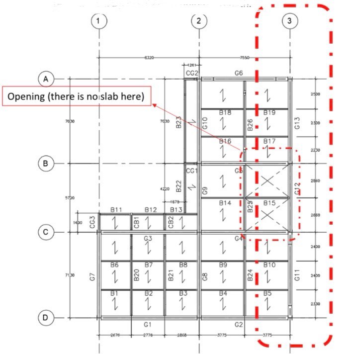
Question: Problem: A continuous girder system as shown in Grid 3 is consists of G 1 1 , G 1 2 and G 1 3 girders.
Problem:
A continuous girder system as shown in Grid is consists of G G and G
girders. The slab resting on these girders have the following superimposed dead
loads:
Metal Deck with Reinforced
Concrete Slab:
Floor Finish Type:
Ceilings Below the Slab:
Hardwood Flooring,
Frame Partitions:
Gypsum board,
Miscellaneous MEPF:
Movable Partitions
Girders G G &G carry a uniform superimposed dead load of kNm
due to the perimeter wall.
The slab carries a live load of Residential Basic Floor Area.
In the initial analysis, beams B B B B & B were assumed to be
Wx Girders G G &G were assumed to be Wx
Earthquake analysis from a software was conducted and the reactions at the
exterior supports joints A & D are as follows:
At joint A:
Shear force VA
Moment MA
At joint D:
Shear force VD
Moment MA
Determine the controlling load combination for LRFD and the
corresponding factored load Shear and Moment in the exterior supports.
If the resistance factor is what is the required nominal strength?
Determine the controlling load combination for ASD and the
corresponding required service load strength Shear and Moment in the
exterior supports.
If the safety factor is what is the required nominal strength based on
the service load strength?
Step by Step Solution
There are 3 Steps involved in it
1 Expert Approved Answer
Step: 1 Unlock

Question Has Been Solved by an Expert!
Get step-by-step solutions from verified subject matter experts
Step: 2 Unlock
Step: 3 Unlock