

Question: Problem D. Referring to the Figure shown in the slide titled Implementation of a RISC Instruction Set (Function Organization, Page 8), discuss all the resources
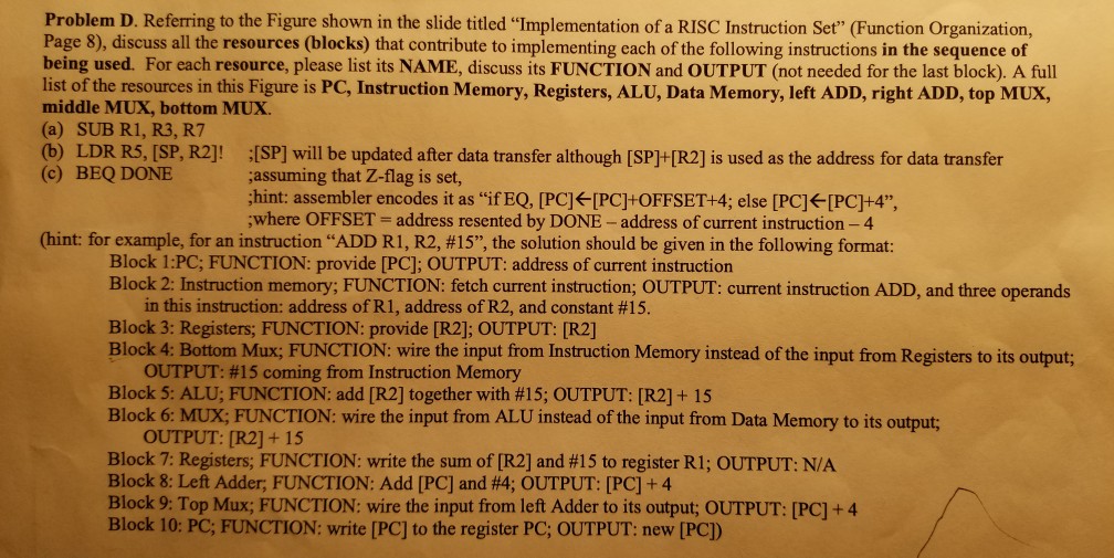
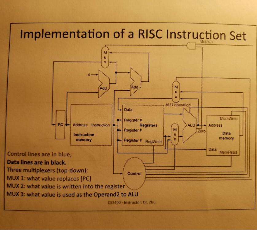
Problem D. Referring to the Figure shown in the slide titled "Implementation of a RISC Instruction Set" (Function Organization, Page 8), discuss all the resources (blocks) that contribute to implementing each of the following instructions in the sequence of being used. For each resource, please list its NAME, discuss its FUNCTION and OUTPUT (not needed for the last block). A full list of the resources in this Figure is PC, Instruction Memory, Registers, ALU, Data Memory, left ADD, right ADD, top MUX, middle MUX, bottom MUX (a) SUB R1, R3, R7 (b) LDR R5, [SP, R2]! [SP] will be updated after data transfer although [SP]+[R2] is used as the address for data transfer (c) BEQ DONE assuming that Z-flag is set, hint: assembler encodes it as "if EQ, [PC] -[PC+OFFSET+4; else [PC] [PC]+4", where OFFSET- address resented by DONE- address of current instruction-4 (hint: for example, for an instruction "ADD RI, R2, #15", the solution should be given in the following format: Block 1:PC; FUNCTION: provide [PC]; OUTPUT: address of current instruction Block 2: Instruction memory; FUNCTION: fetch current instruction; OUTPUT: current instruction ADD, and three operands in this instruction: address ofRI, address of R2, and constant #15 Block 3: Registers; FUNCTION: provide [R2], OUTPUT: [R2] Block 4: Bottom Mux; FUNCTION: wire the input from Instruction Memory instead of the input from Registers to its output; OUTPUT: #15 coming from Instruction Memory Block 5: ALU, FUNCTION: add [R2] together with #15: OUTPUT: [R2] + 15 Block 6 MUM FUNCTION: wire the input from ALU instead of the input from Data Memory to its output; 9 OUTPUT: [R2]+ 15 Block 7: Registers, FUNCTION: write the sum of [R2] and #15 to register RI; OUTPUT: N/A Block 8: Left Adder, FUNCTION: Add [PC] and #4; OUTPUT: [PC] + 4 Block 9: Top Mux; FUNCTION: wire the input from left Adder to its output; OUTPUT: [PC]+4 Block 10: PC, FUNCTION: write [PC] to the register PC, OUTPUT: new [PC]
Step by Step Solution
There are 3 Steps involved in it

Get step-by-step solutions from verified subject matter experts