

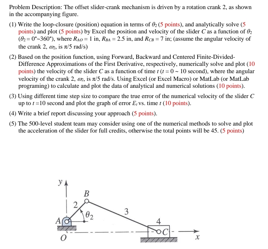
Question: Problem Description: The offset slider - crank mechanism is driven by a rotation crank 2 , as shown in the accompanying figure. PLEASE HELP ME
Problem Description: The offset slidercrank mechanism is driven by a rotation crank as shown
in the accompanying figure.
PLEASE HELP ME SOLVE THROUGH Please look at requirements for each problem
Write the loopclosure position equation in terms of points and analytically solve
points and plot points by Excel the position and velocity of the slider as a function of
where and ; assume the angular velocity of
the crank is
Based on the position function, using Forward, Backward and Centered FiniteDivided
Difference Approximations of the First Derivative, respectively, numerically solve and plot
points the velocity of the slider as a function of time second where the angular
velocity of the crank is Using Excel or Excel Macro or MatLab or MatLab
programing to calculate and plot the data of analytical and numerical solutions points
Using different time step size to compare the true error of the numerical velocity of the slider
up to second and plot the graph of error time points
Write a brief report discussing your approach points
Step by Step Solution
There are 3 Steps involved in it
1 Expert Approved Answer
Step: 1 Unlock

Question Has Been Solved by an Expert!
Get step-by-step solutions from verified subject matter experts
Step: 2 Unlock
Step: 3 Unlock