

Question: Problem No . 1 This exercise will help you refresh your knowledge of statics and prepare you for future exercises on Gerber girder and the
Problem No
This exercise will help you refresh your knowledge of statics and prepare you for future
exercises on Gerber girder and the project.
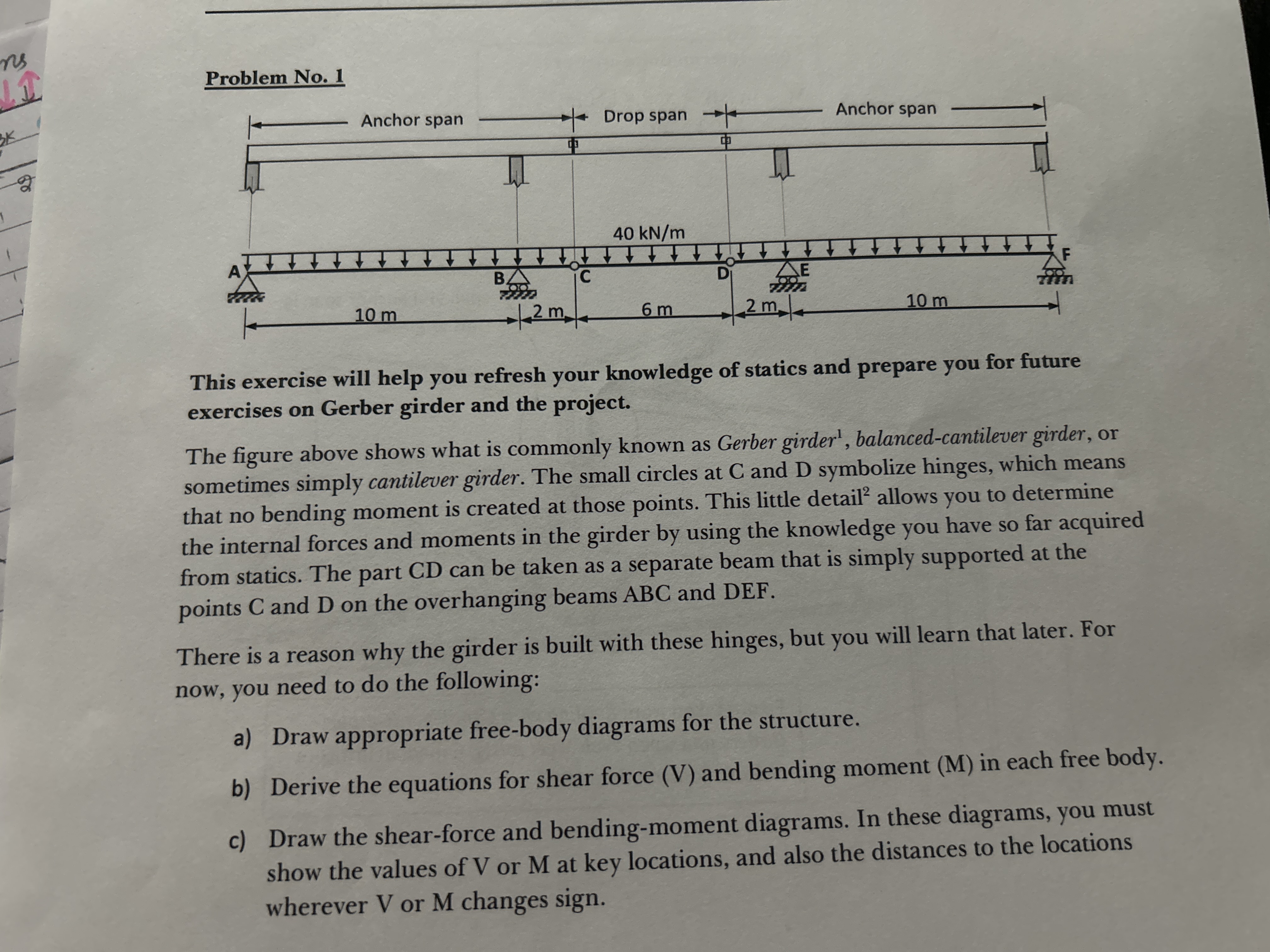
The figure above shows what is commonly known as Gerber girder balancedcantilever girder, or
sometimes simply cantilever girder. The small circles at and symbolize hinges, which means
that no bending moment is created at those points. This little detail allows you to determine
the internal forces and moments in the girder by using the knowledge you have so far acquired
from statics. The part CD can be taken as a separate beam that is simply supported at the
points C and D on the overhanging beams ABC and DEF
There is a reason why the girder is built with these hinges, but you will learn that later. For
now, you need to do the following:
a Draw appropriate freebody diagrams for the structure.
b Derive the equations for shear force V and bending moment M in each free body.
c Draw the shearforce and bendingmoment diagrams. In these diagrams, you must
show the values of V or M at key locations, and also the distances to the locations
wherever or changes sign.
Step by Step Solution
There are 3 Steps involved in it
1 Expert Approved Answer
Step: 1 Unlock

Question Has Been Solved by an Expert!
Get step-by-step solutions from verified subject matter experts
Step: 2 Unlock
Step: 3 Unlock