

Question: Problem statement: A single - phase half - wave circuit is shown with a purely resistive load R . Assume the diode is ideal and
Problem statement:
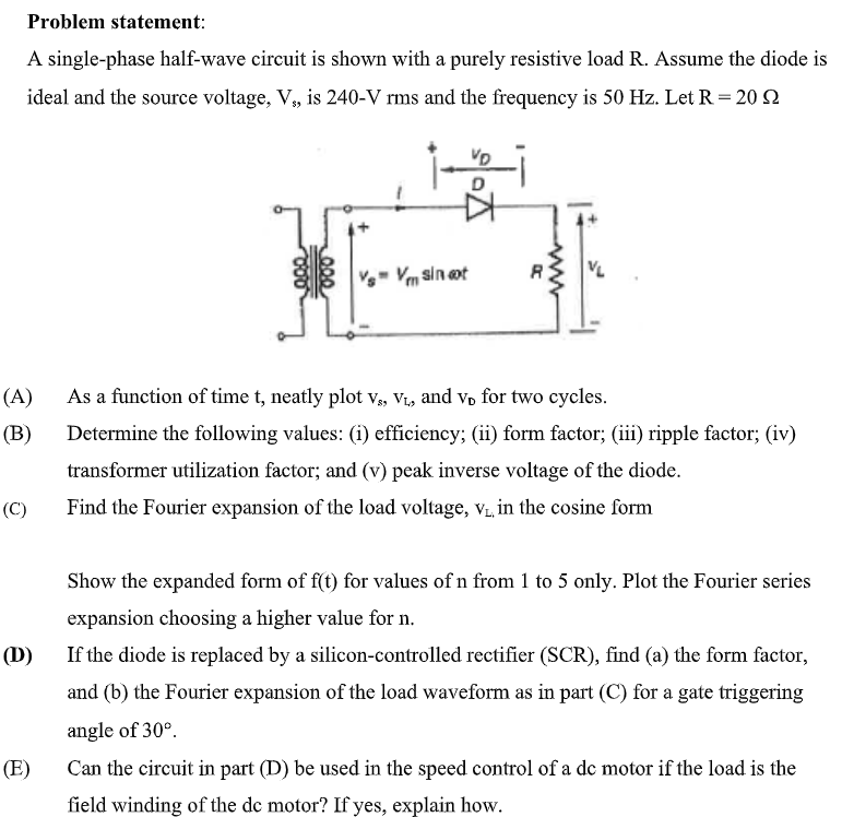
A singlephase halfwave circuit is shown with a purely resistive load R Assume the diode is ideal and the source voltage, mathrmVmathrms is mathrmVmathrmrms and the frequency is Hz Let mathrmROmega
A As a function of time t neatly plot mathrmvmathrmsmathrmvmathrmL and mathrmvmathrmD for two cycles.
B Determine the following values: i efficiency; ii form factor; iii ripple factor; iv transformer utilization factor; and v peak inverse voltage of the diode.
C Find the Fourier expansion of the load voltage, mathrmvmathrmL in the cosine form
Show the expanded form of ft for values of n from to only. Plot the Fourier series expansion choosing a higher value for n
D If the diode is replaced by a siliconcontrolled rectifier SCR find a the form factor, and b the Fourier expansion of the load waveform as in part C for a gate triggering angle of circ
E Can the circuit in part D be used in the speed control of a dc motor if the load is the field winding of the dc motor? If yes, explain how.
Step by Step Solution
There are 3 Steps involved in it
1 Expert Approved Answer
Step: 1 Unlock

Question Has Been Solved by an Expert!
Get step-by-step solutions from verified subject matter experts
Step: 2 Unlock
Step: 3 Unlock