

Question: Problems 6 . 1 Tapped - inductor boost converter. The boost converter is sometimes modified as illustrated in Fig. 6 . 4 1 , to
Problems
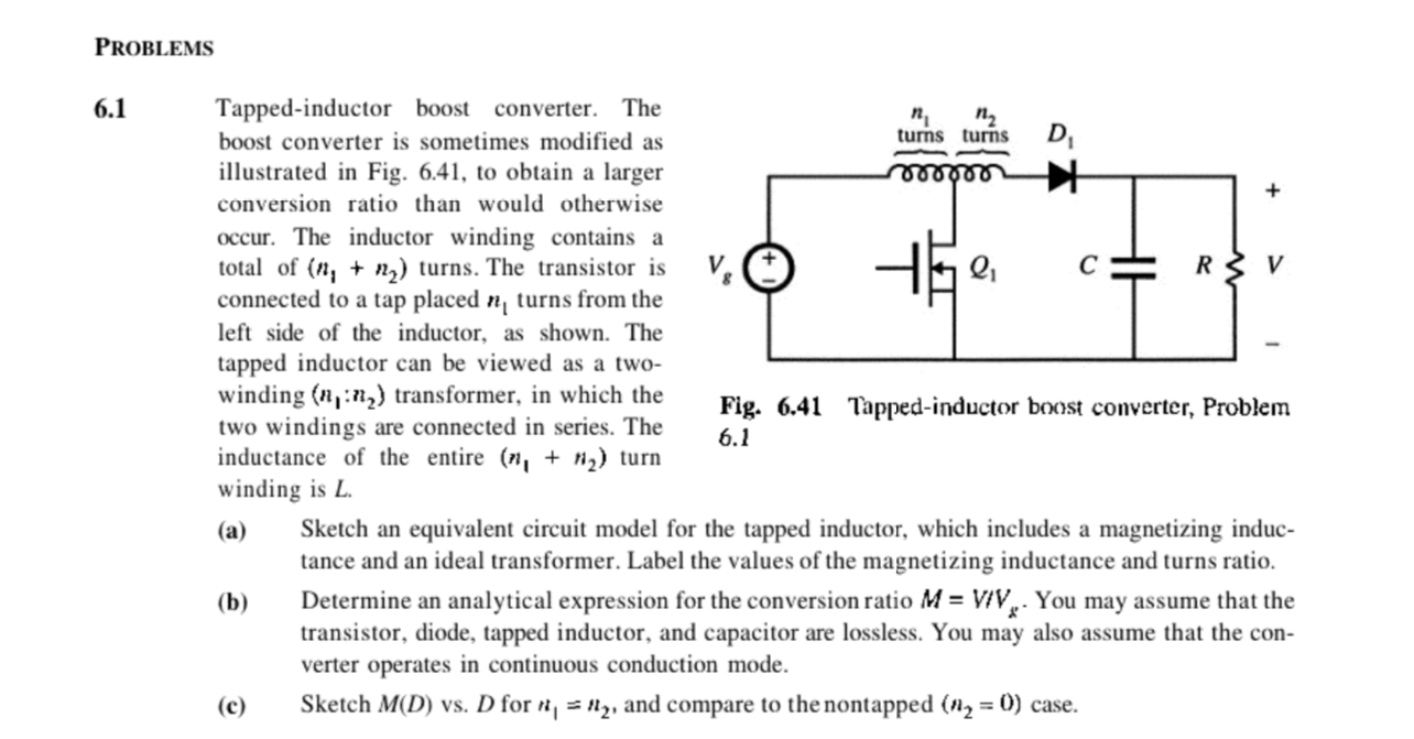
Tappedinductor boost converter. The
boost converter is sometimes modified as
illustrated in Fig. to obtain a larger
conversion ratio than would otherwise
occur. The inductor winding contains a
total of nn turns. The transistor is
connected to a tap placed nn:nnn turn
Fig. Tappedinductor boost converter, Problem
winding is L
a Sketch an equivalent circuit model for the tapped inductor, which includes a magnetizing induc
tance and an ideal transformer. Label the values of the magnetizing inductance and turns ratio.
b Determine an analytical expression for the conversion ratio MVVR You may assume that the
transistor, diode, tapped inductor, and capacitor are lossless. You may also assume that the con
verter operates in continuous conduction mode.
c Sketch MD vs D for nn and compare to the nontapped n case.
Step by Step Solution
There are 3 Steps involved in it
1 Expert Approved Answer
Step: 1 Unlock

Question Has Been Solved by an Expert!
Get step-by-step solutions from verified subject matter experts
Step: 2 Unlock
Step: 3 Unlock