

Question: Procedure Part 1 a . Load Multisim Live in a web browser and sign in . Create a new circuit. b . Place the components
Procedure
Part
a Load Multisim Live in a web browser and sign in Create a new circuit.
b Place the components and wire up the circuit shown in Figure left
Use NMOS transistors not NPN
For both transistors, under model settings, change the L value to n
Use a digital probe to measure the output value PR
In Document settings, change "Mode" to V
Transistor settings:
Modsl
NMOS
table mawChamnel wiater,
Document settings:
Logic ievels
Mriki
V
Oumation
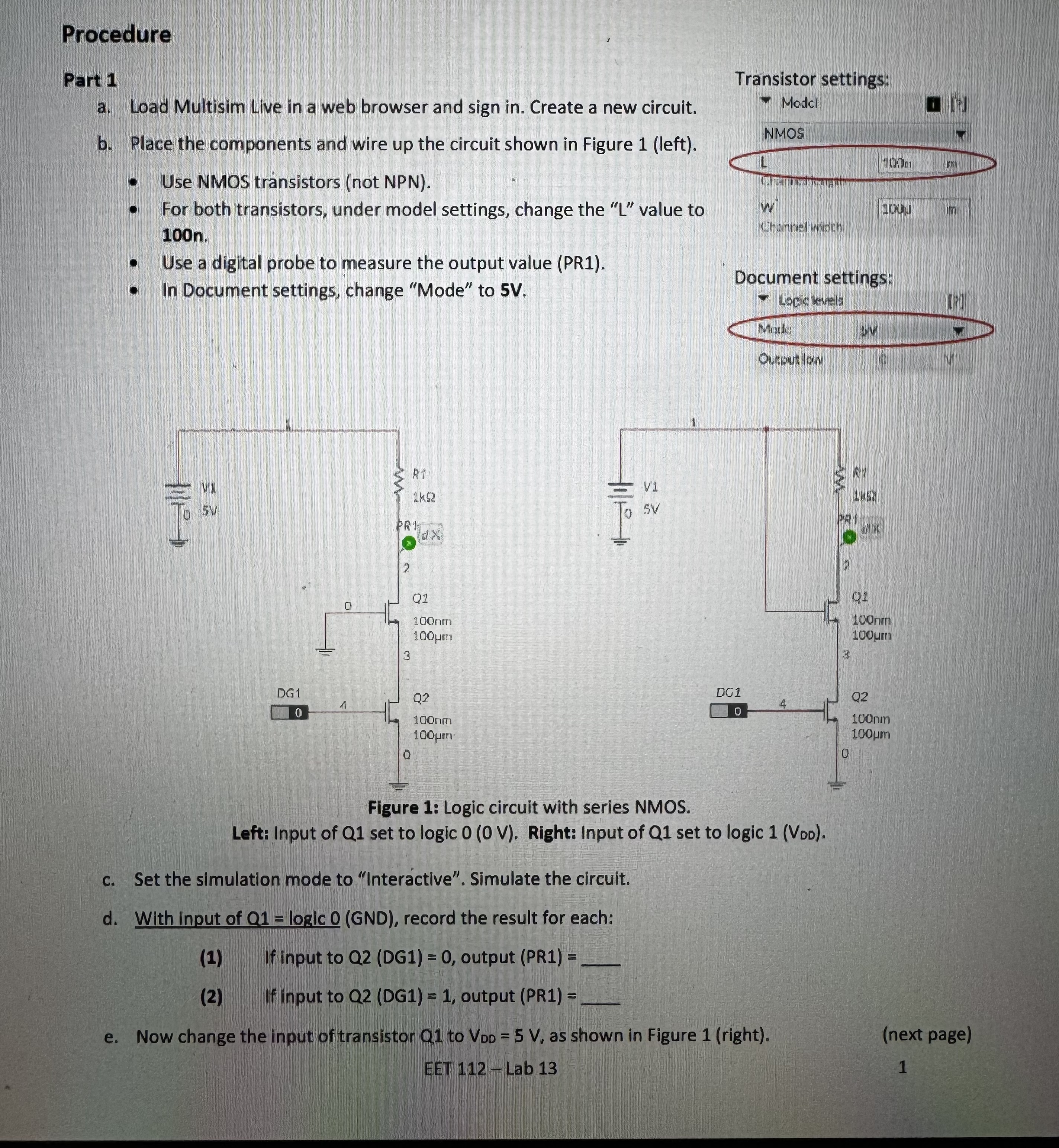
Figure : Logic circuit with series NMOS.
Left: Input of Q set to logic V Right: Input of Q set to logic Voo
c Set the simulation mode to "Interactive". Simulate the circuit.
d With input of logic GND record the result for each:
If input to QDG output PR
If input to QDG output PR
e Now change the input of transistor to as shown in Figure right
next page
EET Lab
I HAVE A SECOND PAGE ASWELL, NO IDEA HOW TO SEND BOTH IN THE SAME QUESTION
Step by Step Solution
There are 3 Steps involved in it
1 Expert Approved Answer
Step: 1 Unlock

Question Has Been Solved by an Expert!
Get step-by-step solutions from verified subject matter experts
Step: 2 Unlock
Step: 3 Unlock