

Question: % Program P2_1 % Simulation of an M-point Moving Average Filter % Generate the input signal n = 0:100 sl cos (2*pi+0.05*n) ; % A
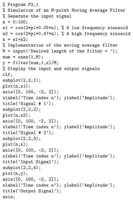
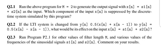
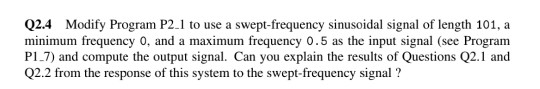
% Program P2_1 % Simulation of an M-point Moving Average Filter % Generate the input signal n = 0:100 sl cos (2*pi+0.05*n) ; % A low frequency sinusoid s2 = cos (2*pi*0.47*n) ; % A high frequency sinusoid x = s1+s2 ; % Implementation of the moving average filter M input ('Desired length of the filter- '); num-ones (1,M); y filter(num , 1,x)/M; % Display the input and output signals clf subplot (2,2,1); plot(n,s1); axis([0, 100, -2, 2]); xlabel('Time index n'); ylabel('Amplitude; title ( Signal # 1 , ) ; subplot (2,2,2); plot (n,s2) axis([0, 100, -2, 2]); xlabel ('Time index n'); ylabel ('Amplitude) title (Signal # 2'); subplot (2,2,3); plot(n,x); axis([0, 100, -2, 2]); xlabel ('Time index n'); ylabel ('Amplitude); title('Input Signal'); subplot (2,2,4); plot (n,y); axis([0, 100, -2, 2]); xlabel ('Time index n'); ylabel('Amplitude); title('Output Signal'); axis Q2.1 Run the above program for M = 2 to generate the output signal with x[n] = s1[n] + s2In] as the input. Which component of the input x [n] is suppressed by the discrete time system simulated by this program? Q2.2 If the LTI system is changed from y[n] 0.5(x[n] x[n 0 . 5 (x [n] -x [n- 1), what would be its effect on the input x [n] 1) to y In] s 1 [n] + s2 [n] ? Q2.3 Run Program P2.1 for other values of filter length M, and various values of the frequencies of the sinusoidal signals s1 [n] and s2[n]. Comment on your results Q2.4 Modify Program P2.1 to use a swept-frequency sinusoidal signal of length 101, a minimum frequency 0, and a maximum frequency 0.5 as the input signal (see Program P1 7) and compute the output signal. Can you explain the results of Questions Q2.1 and Q2.2 from the response of this system to the swept-frequency signal
Step by Step Solution
There are 3 Steps involved in it

Get step-by-step solutions from verified subject matter experts