

Question: Project Data: Setup a smart grid as follows: 8@5ft in the x -direction and 1@5ft in the y -direction Use A36 Gr 36 double angles
Project Data:\ Setup a smart grid as follows:
8@5ftin the
x-direction and
1@5ftin the
y-direction\ Use
A36Gr 36 double angles\ Using the section sets menu create labels for BC, TC, VERT, and DIAG.\ Add
z-translation restraints to all joints\ Add
xand
y-rotational restraints at all joints\ All members are required to have hinges (bending releases) at both ends\ Add -1 to the
y-direction in the basic load cases menu\ Enter dead, live and seismic load categories in the basic loads menu\ Apply Pdead ext
=0.5kand Plive ext
=0.75k. Use Pdead int
=1.0kand Plive int
=1.5k. Apply
Eh=+-2kapplied at the top nodes. Divide the force by the number of top nodes.\ Enter the following load combinations:\
1.2D+1.6L\ 1.2D+1.0Eh
+L\ 1.2DL-1.0Eh
+L\
0.9DL+1.0Eh\ 0.9DL-1.0Eh\ Other load combinations are required for final design but are NOT necessary for this study\ Keep all unity checks below or at 1.0\ Use AISC
360-16strength design\ Vertical deflection
-(L)/(240)for total load\ After suggested shapes are accepted make sure the sizes are not too different size wise for connection design
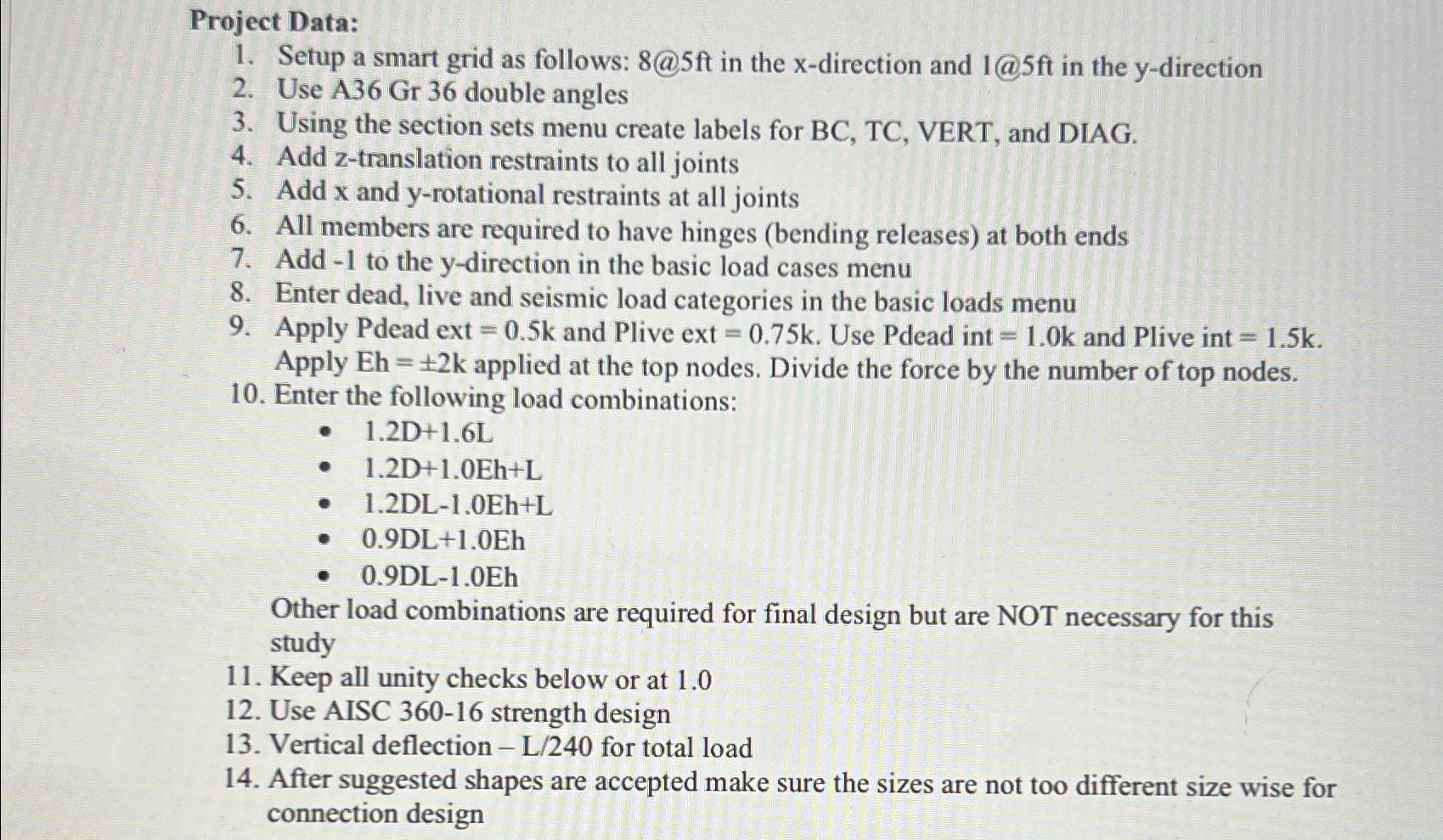
Project Data: 1. Setup a smart grid as follows: 8@5ft in the x-direction and 1@5ft in the y-direction 2. Use A36Gr36 double angles 3. Using the section sets menu create labels for BC, TC, VERT, and DIAG. 4. Add z-translation restraints to all joints 5. Add x and y-rotational restraints at all joints 6. All members are required to have hinges (bending releases) at both ends 7. Add -1 to the y-direction in the basic load cases menu 8. Enter dead, live and seismic load categories in the basic loads menu 9. Apply Pdead ext =0.5k and Plive ext =0.75k. Use Pdead int =1.0k and Plive int =1.5k. Apply Eh=2k applied at the top nodes. Divide the force by the number of top nodes. 10. Enter the following load combinations: - 1.2D+1.6L - 1.2D+1.0Eh+L - 1.2DL-1.0Eh+L - 0.9DL+1.0Eh - 0.9DL1.0Eh Other load combinations are required for final design but are NOT necessary for this study 11. Keep all unity checks below or at 1.0 12. Use AISC 36016 strength design 13. Vertical deflection L/240 for total load 14. After suggested shapes are accepted make sure the sizes are not too different size wise for connection design
Step by Step Solution
There are 3 Steps involved in it

Get step-by-step solutions from verified subject matter experts