

Question: Project Description For project 3, first download the code I have written for you, contained in proj3.zip If you move this file to your CS211
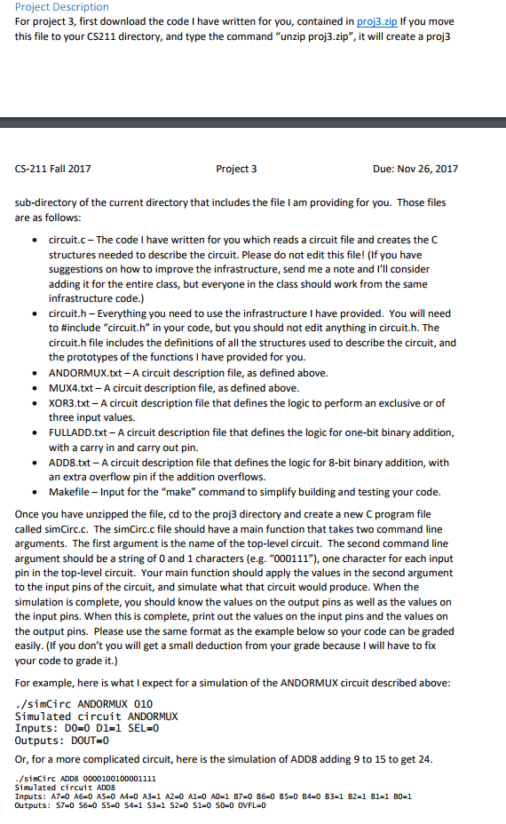
Project Description For project 3, first download the code I have written for you, contained in proj3.zip If you move this file to your CS211 directory, and type the command "unzip proj3.zip", it will create a proj3 CS-211 Fall 2017 Project 3 Due: Nov 26, 2017 sub-directory of the current directory that includes the file I am providing for you. Those files are as follows circuit.c The code I have written for you which reads a circuit file and creates the C structures needed to describe the circuit. Please do not edit this file! (If you have suggestions on how to improve the infrastructure, send me a note and I'll consider adding it for the entire class, but everyone in the class should work from the same infrastructure code.) circuit.h -Everything you need to use the infrastructure I have provided. You will need to #include "circuit. h" in your code, but you should not edit anything in circuith. The circuit.h file includes the definitions of all the structures used to describe the circuit, and the prototypes of the functions I have provided for you. ANDORMUX.txt - A circuit description file, as defined above. MUX4.txt- A circuit description file, as defined above. XOR3.txt-A circuit description file that defines the logic to perform an exclusive or of three input values. FULLADD.txt A circuit description file that defines the logic for one-bit binary addition with a carry in and carry out pin. ADD8.txt-A circuit description file that defines the logic for 8-bit binary addition, with an extra overflow pin if the addition overflows. Makefile Input for the "make" command to simplify building and testing your code. . . . Once you have unzipped the file, cd to the proj3 directory and create a new C program file called simCirc.c. The simCirc.c file should have a main function that takes two command line arguments. The first argument is the name of the top-level circuit. The second command line argument should be a string of 0 and 1 characters (e.g. "000111"), one character for each input pin in the top-level circuit. Your main function should apply the values in the second argument to the input pins of the circuit, and simulate what that circuit would produce. When the simulation is complete, you should know the values on the output pins as well as the values on the input pins. When this is complete, print out the values on the input pins and the values on the output pins. Please use the same format as the example below so your code can be graded easily. (If you don't you will get a small deduction from your grade because I will have to fix your code to grade it.) For example, here is what I expect for a simulation of the ANDORMUX circuit described above /simCirc ANDORMUX 010 Simulated circuit ANDORMUX Inputs: D0-0 D1-1 SEL=0 Outputs: DOUT 0 Or, for a more complicated circuit, here is the simulation of ADD8 adding 9 to 15 to get 24 simCirc ADDS 0000100100001111 Simulated circuit ADD8 Project Description For project 3, first download the code I have written for you, contained in proj3.zip If you move this file to your CS211 directory, and type the command "unzip proj3.zip", it will create a proj3 CS-211 Fall 2017 Project 3 Due: Nov 26, 2017 sub-directory of the current directory that includes the file I am providing for you. Those files are as follows circuit.c The code I have written for you which reads a circuit file and creates the C structures needed to describe the circuit. Please do not edit this file! (If you have suggestions on how to improve the infrastructure, send me a note and I'll consider adding it for the entire class, but everyone in the class should work from the same infrastructure code.) circuit.h -Everything you need to use the infrastructure I have provided. You will need to #include "circuit. h" in your code, but you should not edit anything in circuith. The circuit.h file includes the definitions of all the structures used to describe the circuit, and the prototypes of the functions I have provided for you. ANDORMUX.txt - A circuit description file, as defined above. MUX4.txt- A circuit description file, as defined above. XOR3.txt-A circuit description file that defines the logic to perform an exclusive or of three input values. FULLADD.txt A circuit description file that defines the logic for one-bit binary addition with a carry in and carry out pin. ADD8.txt-A circuit description file that defines the logic for 8-bit binary addition, with an extra overflow pin if the addition overflows. Makefile Input for the "make" command to simplify building and testing your code. . . . Once you have unzipped the file, cd to the proj3 directory and create a new C program file called simCirc.c. The simCirc.c file should have a main function that takes two command line arguments. The first argument is the name of the top-level circuit. The second command line argument should be a string of 0 and 1 characters (e.g. "000111"), one character for each input pin in the top-level circuit. Your main function should apply the values in the second argument to the input pins of the circuit, and simulate what that circuit would produce. When the simulation is complete, you should know the values on the output pins as well as the values on the input pins. When this is complete, print out the values on the input pins and the values on the output pins. Please use the same format as the example below so your code can be graded easily. (If you don't you will get a small deduction from your grade because I will have to fix your code to grade it.) For example, here is what I expect for a simulation of the ANDORMUX circuit described above /simCirc ANDORMUX 010 Simulated circuit ANDORMUX Inputs: D0-0 D1-1 SEL=0 Outputs: DOUT 0 Or, for a more complicated circuit, here is the simulation of ADD8 adding 9 to 15 to get 24 simCirc ADDS 0000100100001111 Simulated circuit ADD8
Step by Step Solution
There are 3 Steps involved in it

Get step-by-step solutions from verified subject matter experts