

Question: Project description: In this project you need to generate an analog signal using LABVIEW and NI myDAQ to drive the DC motor. In addition, an
Project description:
In this project you need to generate an analog signal using LABVIEW and NI myDAQ to drive the DC motor. In addition, an optical encoder installed on the motor will be used to measure the speed rpm of the motor using the counter channel on the DAQ.
Rotary encoders
They are devices sensors mounted on rotating shafts that allow the measurement of the rotational speed of the shaft. There are different types of rotary encoders, the optical encoder being one of them.
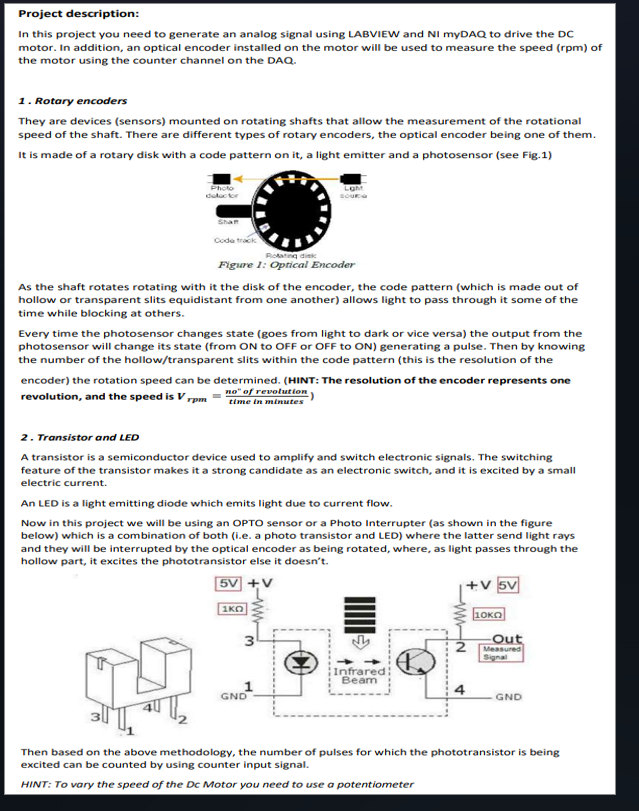
It is made of a rotary disk with a code pattern on it a light emitter and a photosensor see Fig
As the shaft rotates rotating with it the disk of the encoder, the code pattern which is made out of hollow or transparent slits equidistant from one another allows light to pass through it some of the time while blocking at others.
Every time the photosensor changes state goes from light to dark or vice versa the output from the photosensor will change its state from ON to OFF or OFF to ON generating a pulse. Then by knowing the number of the hollowtransparent slits within the code pattern this is the resolution of the encoder the rotation speed can be determined. HINT: The resolution of the encoder represents one revolution, and the speed is Vr p mfracn oprime primetext of revolution text time in minutes
Transistor and LED
A transistor is a semiconductor device used to amplify and switch electronic signals. The switching feature of the transistor makes it a strong candidate as an electronic switch, and it is excited by a small electric current.
An LED is a light emitting diode which emits light due to current flow.
Now in this project we will be using an OPTO sensor or a Photo Interrupter as shown in the figure below which is a combination of both ie a photo transistor and LED where the latter send light rays and they will be interrupted by the optical encoder as being rotated, where, as light passes through the hollow part, it excites the phototransistor else it doesn't.
Then based on the above methodology, the number of pulses for which the phototransistor is being excited can be counted by using counter input signal.
HINT: To vary the speed of the Dc Motor you need to use a potentiometer
Step by Step Solution
There are 3 Steps involved in it
1 Expert Approved Answer
Step: 1 Unlock

Question Has Been Solved by an Expert!
Get step-by-step solutions from verified subject matter experts
Step: 2 Unlock
Step: 3 Unlock