

Question: Provide the Verilog code for a 2-bit Ripple Carry Adder. The block diagram of a 2-bit ripple carry adder is shown below. In a new
Provide the Verilog code for a 2-bit Ripple Carry Adder.
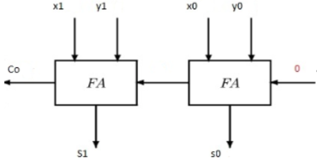
The block diagram of a 2-bit ripple carry adder is shown below. In a new file, describe this structure by instantiating two copies of your myFA modules developed in problem 2. Note that, there is no Cin port in this design and you should connect the Cin port of the first full adder directly to 0. (When instantiating the full adder, in port connection, use 0 for the Cin port.) Name this new module as RippleCarryAdder. It will have 2 input ports: x and y where each of them is a 2-bit wide vector. It will also have 2 output ports: s and Co where s is a 2-bit wide vector and Co is a single bit output. So, the module declaration for this entity should look like the following:
module RippleCarryAdder (x, y, s, Co);
Co x1 y1 FA $1 SO yo FA 0
Step by Step Solution
3.33 Rating (147 Votes )
There are 3 Steps involved in it

Get step-by-step solutions from verified subject matter experts